
Operating instructions

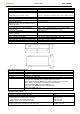


www.pulsar.pl RSFUPS108R RACK POWER
8
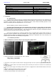
3. Indication of the device operation.
3.1. LED indication of operating status.
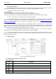
The PSU has 6 LED lights at the front panel:
GREEN LED:
on – the PSU is supplied with 230 V
off – no 230 V supply
GREEN LED:
on – DC voltage at the output of the switch mode PSU
off – no DC voltage at the output of the switch mode PSU
RED LED:
on – failure
off – no failure
RED LED:
ON – too high temperature of the switch mode power supply
(>70 °C)
OFF – standard temperature of the switch mode power supply
RED LED:
on – battery voltage <23 V
off – battery voltage >23 V
GREEN LED:
ON – DC voltage at the NVR output
OFF - no DC voltage at the NVR output
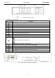
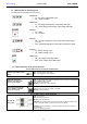
3.2. Optical indication of the switch operation:
OPTICAL INDICATION OF THE SWITCH's POWER SUPPLY
GREEN LED LIGHT (Power)
Indication of the switch's power
supply
OFF – no power supply of the switch
ON – power supply on, normal operation
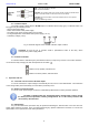
OPTICAL INDICATION OF THE SWITCH's POWER SUPPLY (1÷8)
GREEN LED LIGHT (PoE)
Indication of the PoE power
supply at the RJ45 ports
OFF- no power supply at the RJ45 port (the device is not connected or not compliant
with the IEEE802.3af/at standard)
ON – supply at the RJ45 port
Blinking – short-circuit or output overload
YELLOW LED LIGHT (LINK)
The connection status of LAN
devices, 10 MB/s or 100 Mb/s
and data transmission
OFF- no connection
ON - the device is connected; 10 Mb/s or 100 Mb/s
Blinking – data transmission
OPTICAL INDICATION AT THE UPLINK PORTS
YELLOW LED
LIGHT (LINK)
OFF- no connection
ON - the device is connected
Blinking – data transmission
CAUTION! The operating status of the G1/TP, G1/SFP, G2/TP and G2/SFP slots is
shown on the LEDs located near the RJ45 connector (see below).
CAUTION! G1/TP and G1/SFP or G2/TP and G2/SFP sockets can not operate
simultaneously.
These are COMBO type sockets.