
Operating instructions


www.pulsar.pl RSFUPS108R RACK POWER
3
1. Technical description.
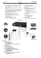
1.1. General description.
The RSFUPS108R is a complete solution for power supply and battery backup of 8 IP cameras (52 V DC power
supply) and uninterruptible power supply of the DVR (12 V DC power supply) in RACK 19" standard.
The main elements of this system include:
- 10 port PoE switch
- buffer power supply 27,6 V unit which can accommodate two 12 V batteries
- a converter (DC/DC52230) increasing the voltage to 52 V DC (supply of the PoE switch)
- a buck converter (step-down converter) (DC/DC50SD) lowering voltage to 12 V DC (recorder power supply).
In case of mains power loss, a battery back-up is activated immediately.
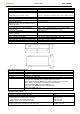
The approximate backup time is given assuming that all output ports are used (using typical devices and 28Ah
batteries). The electricity consumption for own needs and the energy efficiency of the power intake track were taken into
account. The exact description of how to perform the calculations can be found at: "Approximate backup time -
assumptions for calculations".
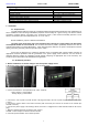
Automatic detection of any devices powered in the PoE/PoE+ standard is enabled at the 1 – 8 ports of the
switch. The G1/TP, G2/TP ports is used for connection of another network device via RJ45 connector. The switch is fitted
with SFP slots (marked as G1/SFP and G2/SFP); the use of fiber optic module (GBIC) allows fiber optic transmission.
The LED lights at the front panel indicate the operating status of the device.
The switch is fitted with the ALARM technical output of collective failure. In the case of failure, a LED light is
activated, which is accompanied by switching of relay contacts and acoustic indication.
The PoE technology ensures a network connection and reduces installation costs by eliminating the need to
supply a separate power cable for each device. This method allows supplying other network devices, such as IP phone,
wireless access point or router.
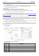
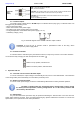
1.2. Block diagram.
Fig.1. The block diagram of the PSU.
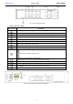
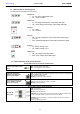
1.3. Description of components and connectors.
Table 1. (See Fig. 2).
Element no.
[Fig. 2]
Description
LINK - yellow LED - indicating the LAN connection status
PoE - green LED indicating voltage at the PoE port
PWR – green LED indicating the supply voltage of the Switch
PoE port 1÷8 for cameras IP connection (data + power supply)
2 x UPLINK ports (G1/TP, G2/TP)
2 x UPLINK ports (G1/SFP, G2/SFP)