
User Instructions

www.pulsar.pl RSFUPS108 RACK POWER
5
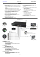
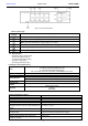
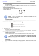
Fig.5. The view of the switch.
Table 2. (See Fig. 5).
Element no.
[Fig. 2]
Description
LINK - yellow LED - indicating the LAN connection status
PoE - green LED indicating voltage at the PoE port
PWR - green LED indicating the supply voltage of the Switch
PoE port 1÷8 for cameras IP connection (data + power supply)
2 x UPLINK ports (G1/TP, G2/TP)
2 x UPLINK ports (G1/SFP, G2/SFP)
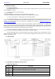
1.4. Specifications.
- parameters of the switch (tab.3)
- electrical parameters (tab.4)
- mechanical parameters (tab.5)
- operation safety (tab.6)
- operating parameters (tab.7)
Parameters of the switch (tab. 3).
Ports
8 x PoE (10/100 Mb/s) (RJ-45)
2 x UPLINK (10/100/1000 Mb/s) (RJ-45)
2 x UPLINK (10/100/1000 Mb/s) (SFP)
with connection speed auto-negotiation and MDI/MDIX Auto Cross)
PoE power supply
IEEE802.3af/at (1÷8 ports), 52 V DC / 30 W at each port *
Protocols, Standards
IEEE802.3, 802.3u, 802.3 x CSMA/CD, TCP/IP
Forwarding rate
10BASE-T: 14880 pps/port
100BASE-TX: 148800 pps/port
Bandwidth
1,6 Gbps
Transmission
method
Store-and-Forward
Optical indication of
operation
Switch power supply;
Link/Act;
PoE Status
* The given value of 30 W per port is the maximum value. The total power consumption should not exceed 96 W.
Electrical parameters (tab. 4).
Mains supply
~230 V; 50 Hz
Current up to
1,1 A
Supply power
110 W max.
Output voltage at the PoE ports
52 V DC – maintained regardless of the state of battery charge
The output current at the PoE ports
8 x 0,6 A Ʃ=2 A (max.)
Battery charge current
(batteries 2x7 Ah / 2x17 Ah, connect batteries in
series)
0,5 A max. (+/-5 %)
Approximate backup time
5 h 30 min
Short-circuit protection SCP and overload
protection OLP
105 % ÷ 150 % of the PSU power, manual restart (failure
requires the disconnection of the DC output)
PSU current consumption
200 mA/27,6 V
Battery circuit protection SCP and reverse
polarity connection
melting fuse