
User Instructions


www.pulsar.pl RPUPS1248R RACK POWER
7
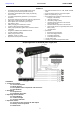
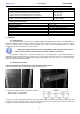
Fig. 4. Connection of network devices to the LAN and POE terminals.
5. Connect the power supply of the recorder to the NVR connector.
6. If needed, the following technical connections can be made:
- ALARM – technical output of collective failure
7. Connect the ~230V AC power cord with the IEC C13 plug (included) to the 230V AC power supply and turn on the
power (~230V).
8. Check the PSU operation indicator.
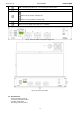
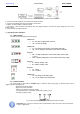
3. Operating status indication.
3.1. LED indication.
The PSU has 6 LED lights at the front panel:
GREEN LED:
on – the PSU is supplied with 230V AC
off – no 230V AC supply
GREEN LED:
on – DC voltage at the output of the switch mode PSU
off – no DC voltage at the output of the switch mode PSU
RED LED:
ON – too high temperature of the switch mode power supply
(>70°C)
OFF – standard temperature of the switch mode power supply
RED LED:
on – battery voltage <46V
off – battery voltage >46V
RED LED:
on – failure
off – no failure
GREEN LED:
on – DC voltage in the NVR output
off – no DC voltage in the NVR output
3.2. Technical output.
The power supply is fitted with the ALARM output of collective failure (relay type). A collective failure can be
triggered by the following events:
- 230V AC mains power failure
- polymer fuses PTC activation
- Failure of the switch mode power supply
- Too high temperature of the switch mode power supply (>70°C)
- Low battery voltage (<46V)
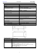
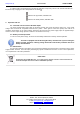
Fig. 5. Electrical diagram of the ALARM collective output of failure.
CAUTION! In Fig. 5 the set of contacts shows a potential-free status of the relay, which corresponds
to power supply failure.