
User Instructions


www.pulsar.pl RPUPS1248R RACK POWER
6
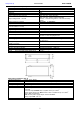
Operation safety (tab.4).
Protection class PN-EN 60950-1:2007
I (first)
Protection grade PN-EN 60529: 2002 (U)
IP20
Electrical strength of insulation:
- between input and output circuits of the PSU (I/P-O/P)
- between input circuit and PE protection circuit (I/P-FG)
- between output circuit and PE protection circuit (O/P-FG)
3000 V/AC min.
1500 V/AC min.
500 V/AC min.
Insulation resistance:
- between input circuit and output or protection circuit
100 MΩ, 500V/DC
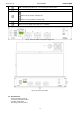
Operating parameters (tab.5).
Environmental class
II
Operating temperature
-10ºC...+45ºC
Storage temperature
-20ºC...+60ºC
Relative humidity
20%...90%, without condensation
Vibrations during operation
unacceptable
Impulse waves during operation
unacceptable
Direct insulation
unacceptable
Vibrations and impulse waves during transport
According to PN-83/T-42106
2. Installation.
2.1. Requirements.
The PSU RACK shall be mounted by a qualified installer with appropriate permissions and qualifications for
230V AC installations and low-voltage installations (required and necessary for a given country). The device shall be
mounted in confined spaces, according to the environment class II, with normal air humidity (RH=90% max. without
condensation) and the temperature from -10°C do +45°C.
During normal operation the total current consumption of the receivers cannot exceed
I=3,5A. The maximum current drawn by the recorder should not exceed 4A.
As the PSU is designed for a continuous operation and is not equipped with a power-switch, therefore an
appropriate overload protection shall be guaranteed in the power supply circuit. Moreover, the user shall be informed
about the method of unplugging (usually through assigning an appropriate fuse in the fuse-box). The electrical system
shall follow valid standards and regulations.
2.2. Installation procedure.
1. Before installation, cut off the voltage in the 230V power-supply circuit.
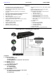
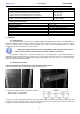
2. Mount the power supply in a RACK 19" cabinet as shown below:
- Mount M6 cage nuts
- Secure the enclosure with 4xM4 screws
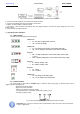
3. Connect the battery in series to the +BAT- terminals:
- battery output (+): terminal BAT+
- battery output (-): terminal BAT-
4. Connect the network cables (Ethernet) to the PoE, LAN module: supply voltage is present only at the PoE sockets and
the devices should be connected to them. Connect the Ethernet signal from the network switch to LAN connectors. Pin
assignment of the LAN and POE sockets is shown in the Figure 4: