
User Instructions
www.pulsar.pl ROUPS12VR RACK POWER CCTV
3
CONTENTS:
1. Technical description.
1.1. General description
1.2. Block diagram
1.3. Description of PSU components and connectors
1.4. Specifications
2. Installation.
2.1. Requirements
2.2. Installation procedure
3. Operating status indication.
3.1. LED indication
3.2. Technical output
3.3. Acoustic indication
4. Operation and use.
4.1. Overload or short circuit of the PSU output
4.2. Battery-assisted operation
4.3. Maintenance
1. Technical description.
1.1. General description.
The ROUPS12VR buffer power supply unit is designed for uninterrupted power supply of up to recorder
requiring stabilized voltage of 12V DC. The PSU provides voltage of U=12V DC current efficiency max. I=5A + 1A
battery charge. In case of power decay, a battery back-up is activated immediately. The output for the recorder is
protected with a 5A polymer fuse. The power supply is fitted with the ALARM output of collective failure. In case of
failure, relay contacts are switched automatically, which is accompanied by acoustic and optical indication (the
corresponding led goes on). The power supply construction is based on the switch mode PSU with high energy
efficiency and is located in an enclosure adapted for mounting in standard RACK 19” cabinets.
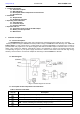
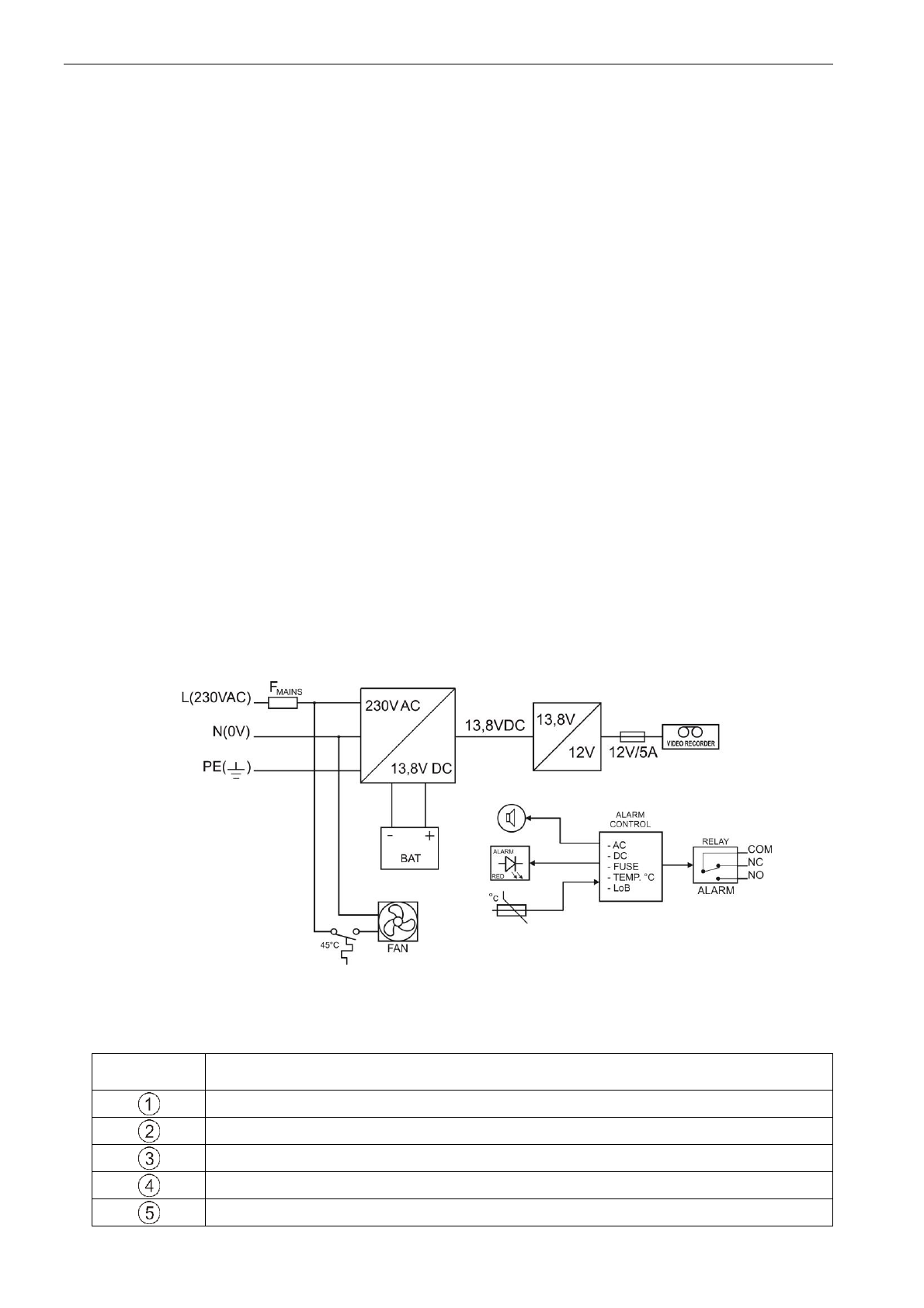
1.2. Block diagram.
Fig.1. The block diagram of the PSU.
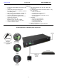
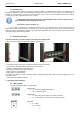
1.3. Description of PSU components and connectors.
Table 1. Elements of the PSU.
Element no.
[Fig. 2]
Description
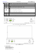
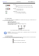
AC OK – green LED, indicating the presence of 230V voltage
DC OK – green LED, indicating the presence of DC voltage
TEMP – red LED, indicating too high temperature of the power supply (>70°C)
LoB – red LED, indicating too low battery voltage (<11,5V)
LED ALARM – red LED failure indication