
User Instructions

www.pulsar.pl RN500
4
2. Installation
2.1 Requirements.
The module of the reducer is to be mounted by a qualified installer, holding relevant permits and licenses (applicable and
required for a given country) for low-voltage installations. The unit should be mounted in confined spaces, in accordance with the
2nd environmental class, with normal relative humidity (RH=20%-90% maximum, without condensation) and temperature from -
10°C to +40°C. The module shall work in such a position that guarantees sufficient convectional air-flow through around the
reducer.
Before the installation, perform a load balance of the reducer. During normal operation, total current drawn by
the receivers cannot exceed I=5A (P=60W max.). For proper operation, an appropriate current efficiency of the power
source shall be guaranteed. The power source (a PSU) must feature its own short-circuit protection (SCP) and an
overload protection (OLP).
The device should be installed in a metallic enclosure (cabinet). In order to meet the LVD and EC requirements, the rules
concerning: supply, development and shielding ought to be followed- accordingly to the application.
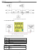
2.2 Installation procedure.
1. Install the enclosure, (a cabinet, etc.) and lead the cables through the cable ducts.
2. Mount the RN500 voltage reducer (a mounting panel with an adhesive tape, dowel pins x 4 ).
3. Deliver the DC power to +IN, -IN terminals, keeping polarisation.
4. Connect the receivers’ cables to the +AUX, -AUX terminals, keeping polarisation.
5. Switch on the DC supply (IN red diode and AUX green diode should be continuously lit).
6. Check the output voltage (nominal voltage of the reducer shall amount to 12V). If the value of the maximum voltage requires
adjustment, it should be set by the P1 potentiometer, monitoring the voltage at the AUX output of the reducer.
7. Once the tests and operation control have been completed, the enclosure/cabinet can be locked.
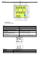
3. Reducer’s operating status indication.
3.1. LED indication.
The reducer is equipped with two LEDs: IN, AUX indicating operating status.
IN- red diode: under normal status (DC supply) the diode is permanently illuminated. The absence of DC supply is
indicated by the IN diode going out.
AUX- green diode: indicates the DC supply status at the output of the reducer. Under normal status, the diode is
permanently illuminated. In case of a short circuit or an overload the diode is off.
4. Operation and use.
4.1. Overload or short circuit at the reducer’s output.
In case of a short circuit in the AUX, BAT output, there is an automatic disconnection of the output voltage which is
indicated by the AUX diode going out. This requires disconnection of the load from the reducer’s output for approx. 1 minute.
4.2. Maintenance.
The reducer does not require performing any specific maintenance measures. However, in case of a significant level of
dust, clean the device with compressed air.
Pulsar
Siedlec 150, 32-744 Łapczyca, Polska
Tel. (+48) 14-610-19-40, Fax. (+48) 14-610-19-50
e-mail: biuro@pulsar.pl, sales@pulsar.pl
http:// www.pulsar.pl, www.zasilacze.pl
WEEE MARKING
According to the EU WEE Directive – It is required not to dispose of electric or electronic waste as unsorted municipal waste and to collect
such WEEE separately.