
User Instructions

www.pulsar.pl RN500
2
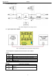
1.2. Block diagram (fig.1).
Fig.1. Block diagram of the voltage reducer.
1.3. Typical application of RN500.
FIg.2. Typical application of the RN500 voltage reducer.
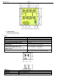
1.4. Description of components and connectors of the reducer.
Table 1.
No.
[fig.3]
Element description
[1]
IN LED – red (reducer’s power status)
[2]
+IN-, +AUX-, connectors of the reducer (see tab.2)
[3]
AUX LED – green (reducer’s output status)
[4]
P1 potentiometer, voltage adjustment (11-Uin)
[5]
Mounting strip
Table 2.
[2]
Connectors description
+IN
- IN
DC power input (+IN= +U, -IN=GND, 0V), 9V-14V DC
stabilised
+AUX
- AUX
DC power output (+AUX= +U, -AUX=GND), voltage
U<12V DC