
User Instructions

www.pulsar.pl RCB12V RACK POWER
3
1. Technical description.
1.1. General description.
The RCB12V battery controller is designed for monitoring the status of the 4x17Ah/12V (SLA) battery pack
based on the measurements of resistance, continuity of the battery circuit, voltage, and the charge level. It is also
protected against reverse connection and short circuit in the charging circuit. In the case of failure, a LED light is
activated, which is accompanied by switching of relay contacts and acoustic indication.
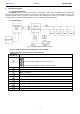
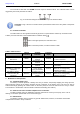
1.2. Block diagram.
Fig.1. The block diagram of the controller.
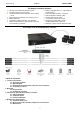
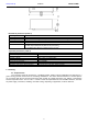
1.3. Description of elements and connectors of the controller
Table 1. Elements of the front panel of the controller.
Component
No. [Fig. 2]
Description
BUZZER, micro switch, enable/disable the acoustic indication
Switch in the upper position, the indication is ON
Switch in the lower position, acoustic indication is OFF
ALARM – Technical output of collective failure - relay type
LED ALARM – red LED indicating failure
TEST – test button
BAT – connector of the charging circuit
A battery compartment for BAT1 battery
A battery compartment for BAT2 battery
A battery compartment for BAT3 battery
A battery compartment for BAT4 battery
Battery cables (+ BAT red, -BAT black)
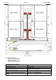
Mounting brackets (adjustable)