
User Instructions


www.pulsar.pl RC24V RACK POWER
6
2. Indication of operation of the battery controller.
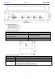
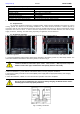
3.1. Optical indication.
The controller is equipped with LED light at the front panel:
RED LED:
ON/blinking – Indicates a failure (Table 6)
OFF – No errors/normal operation
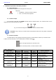
3.2. Technical output.
The controller is fitted with the ALARM technical output of collective failure. The collective failure can be
triggered by the events presented in Table 6.
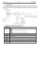
Fig. 6. The electrical diagram of the ALARM output of collective failure.
CAUTION! In Fig. 6 the set of contacts shows a potential-free status of the relay which corresponds
to a failure.
3.3. Acoustic indication.
The failure status is also signaled acoustically by means of a piezoelectric indicator (in accordance with
Table 6). Acoustic indication can be disabled with an ON/OFF switch .
Switch in the upper position, the indication is ON
Switch in the lower position, acoustic indication is OFF
Table 6. Table of errors
State, failure
Optical
indication
Acoustic
indication
Technical
output
Causes, comments
The start of the test
Absence
2 short beeps
INACTIVE
- Start of the battery test
High resistance of the
BAT circuit
Blinks
1 beep every 10
seconds
ACTIVE
- Batteries worn out
- Loose connectors
Undercharged battery
Blinks
1 beep every 10
seconds
ACTIVE
- Undercharged battery
No battery
Blinks
1 beep every 10
seconds
ACTIVE
- Blown F
BAT
fuse
- No battery
Low battery voltage (DC
operation)
Lit
2 short beeps
every 10 seconds
ACTIVE
- The batteries voltage has
dropped below 23V during battery
(assisted operation)
Low battery voltage -
disconnection (DC
operation)
Absence
2 beeps every 10
seconds (without
repeat)
ACTIVE
- The batteries voltage has
dropped below 21V during battery
(assisted operation)