
User Instructions

www.pulsar.pl RC24V RACK POWER
2
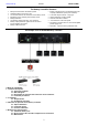
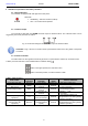
The battery controller features:
Microprocessor-based automation system
Automatic battery test every 5 min.
The measurement of the resistance of the battery circuit
Monitoring of the continuity of the battery circuit
Battery Detection
Low battery voltage indication - DC operation
Battery output protection against short-circuit and
reverse polarity connection
Battery cables included
Battery compartment for 2÷4 batteries
(the total
capacity of 80Ah/12V (SLA) max. batteries)
Technical output of failure - relay type
Optical indication of failure (LED)
Acoustic indication of failure
"Test" button is at the front panel
Designed to operate with a 27,6V uninterruptible
power supply unit
Warranty - 2 years from the production date
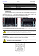
An example of use of the RACK battery controller.
TABLE OF CONTENTS:
1. Technical description.
1.1. General description
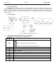
1.2. Block diagram
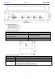
1.3. Description of elements and connectors of the controller
1.4. Technical parameters
2. Installation.
2.1. Requirements
2.2. Installation procedure
3. Indication of operation of the battery controller.
3.1. Optical indication
3.2. Technical output
3.3. Acoustic indication
4. Maintenance and operation.
4.1. Automatic battery test
4.2. Short circuit of the controller output/reverse connection
4.3. Maintenance