
User Instructions

www.pulsar.pl R1612T RACK POWER
6
During normal operation the total current consumption of the receivers cannot exceed I=14A.
As the PSU is designed for a continuous operation and is not equipped with a power-switch, therefore an
appropriate overload protection shall be guaranteed in the power supply circuit. Moreover, the user shall be
informed about the method of unplugging (usually through assigning an appropriate fuse in the fuse-box). The
electrical system shall follow valid standards and regulations.
2.2. Installation procedure.
1. Before installation, cut off the voltage in the 230V power-supply circuit.
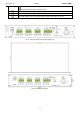
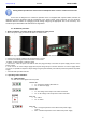
2. Mount the power supply in a RACK 19" cabinet as shown below:
- Mount M6 cage nuts
- Secure the enclosure with 4xM6 screws
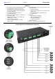
3. Connect the receivers’ cables to the terminals AUX1...AUX16.
4. If needed, the following technical connections can be made:
- ALARM – technical output of collective failure
5. Connect the ~230V AC power cord with the IEC C13 plug (included) to the 230V AC power supply and turn on the
power (~230V).
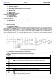
6. In the case of an unsafe voltage supply with frequent voltage drops in effective resistance of receiver supply cables
can occur, it is possible to adjust the output voltage using the potentiometer (12V÷15V DC) at the front panel of the power
supply.
7. Check the PSU operation indicator.
3. Operating status indication.
3.1. LED indication.
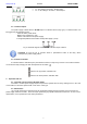
The PSU has 20 LED lights at the front panel:
GREEN LED:
on – the PSU is supplied with 230V AC
off – no 230V AC supply
GREEN LED:
on – DC voltage at the output of the switch mode PSU
off – no DC voltage at the output of the switch mode PSU
RED LED:
on – failure
off – no failure
RED LED:
ON – too high temperature of the switch mode power supply
(>70°C)
OFF – standard temperature of the switch mode power supply