
User Instructions

www.pulsar.pl R1612T RACK POWER
3
CONTENTS:
1. Technical description.
1.1. General description
1.2. Block diagram
1.3. Description of PSU components and connectors
1.4. Specifications
2. Installation.
2.1. Requirements
2.2. Installation procedure
3. Operating status indication.
3.1. LED indication
3.2. Technical output
3.3. Acoustic indication
4. Operation and use.
4.1. Overload or short circuit of the PSU output
4.2. Maintenance
1. Technical description.
1.1. General description.
The R1612T power supply unit is designed for uninterrupted power supply of up to 16 HD cameras requiring
stabilized voltage of 12V DC with the total current efficiency of 14A. The output voltage adjustment range is
adjusted via a potentiometer within the range of 12V÷15V DC. The PSU is fitted with 16 outputs protected
independently with melting fuse 1,5A. The power supply is fitted with the ALARM output of collective failure. In
case of failure, relay contacts are switched automatically, which is accompanied by acoustic and optical indication
(the corresponding led goes on). The power supply construction is based on the switch mode PSU with high
energy efficiency and is located in an enclosure adapted for mounting in standard RACK 19” cabinets.
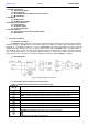
1.2. Block diagram.
Fig.1. The block diagram of the PSU.
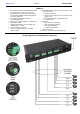
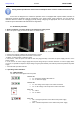
1.3. Description of PSU components and connectors.
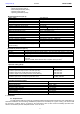
Table 1. Components of the front panel of the power supply.
Element no.
[Fig. 2]
Description
AC OK – green LED, indicating the presence of 230V voltage
DC OK – green LED, indicating the presence of DC voltage
TEMP – red LED, indicating too high temperature of the power supply (>70°C)
Green LED AUX1 ÷ AUX16 – voltage indication at the outputs AUX
LED ALARM – red LED failure indication
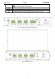
AUX1 ÷ AUX16 – independently protected outputs
ALARM – technical output of collective failure – relay
Potentiometer, output voltage adjustment within the range of 12V÷15V DC
BUZZER, micro switch, turning ON / OFF of acoustic indication
switch in the top position, indication ON