
User Instructions


www.pulsar.pl PSDCB09129C
4
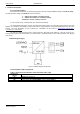
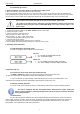
Fig. 2. The view of the fuse block LB9.
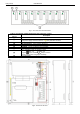
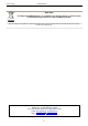
Table 2. Description of PSU components and connectors ( tab.2)
Element no.
[Fig. 3]
Description
[1]
PSU module
[2]
L-N power-supply connector 230V AC, PE protection connector
[3]
green LED indicates AC power
[4]
P1 potentiometer, output voltage adjustment
[5]
BAT+/GND: battery outputs + BAT=red, - GND=black
[6]
TAMPER, contact of sabotage protection (NC)
[7]
Additional connector for LED indication
[8]
Ibat - Selection jumper for charging current:
Ibat =1A Ibat =4A
Legend: jumper installed, jumper removed.
Factory settings: Ibat =1A (jumper installed).
[9]
Fuse block LB9
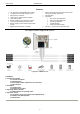
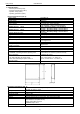
Fig.3. The view of the PSU.