
User Instructions


www.pulsar.pl PSDCB09129C
3
1. Technical description.
1.1 General description.
A buffer PSU is intended for an uninterrupted supply to devices requiring stabilised voltage of 12V DC (+/-15%).
The PSU provides voltage of U=13,8V DC. Current efficiency:
1. Output current 9x1A + 1A battery charge
2. Output current 9x0,77A + 4A battery charge
Total device current + battery: 11A max
*
.
In case of power decay, a battery back-up is activated immediately.
The approximate backup time is given assuming that all output ports are used (using typical devices and 17Ah
batteria). The electricity consumption for own needs and the energy efficiency of the power intake track were taken into
account. The exact description of how to perform the calculations can be found at: "Approximate backup time -
assumptions for calculations".
The PSU is constructed based on the switch mode PSU, with high energy efficiency. The PSU is housed in a
metal enclosure (colour RAL 9003) which can accommodate a 17Ah/12V battery. A micro switch indicates door opening
(front cover).
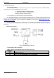
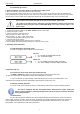
1.2 Block diagram (fig.1)
Fig.1. The block diagram of the PSU.
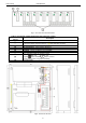
1.3 Description of PSU components.
Table 1. Elements and connectors of the fuse block (tab.1, fig.2).
Element no.
[fig. 2]
Description
[1]
F1÷F9 glass fuses PTC
[2]
LED L1 ÷ L9 signaling presence of output voltage DC
[3]
power supply output AUX1÷AUX9, shared terminal COM (-)
*
Refer to chart 1