
User Instructions
www.pulsar.pl PSDC161214
4
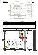
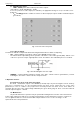
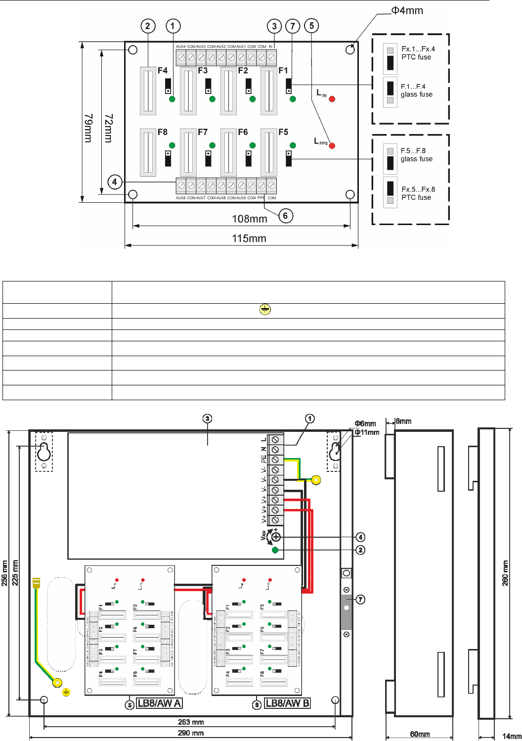
Fig.2. The view of the PSU’s PCB.
Table 2. Elements of the PSU (see fig. 3).
Element no.
Description
[1]
L-N 230V AC power connectors, PE protection connector
[2]
LED indication
of DC power status, main module of the PSU
[3]
PSU module
[4] V
ADJ
, potentiometer, output voltage adjustment within the range of 12V÷15V DC
[5] LB8/AW-A fuse strip, with power outputs and LED indication
[6] LB8/AW-B fuse strip, with power outputs and LED indication
[7] Tamper, contact of tampering protection (NC)
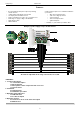
Fig.3. The view of the PSU.