
User Instructions

www.pulsar.pl PSDC08128T
6
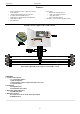
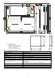
4. Connect the receivers’ cables to the AUX1…AUX8 connectors on the LB8 strips.
5. In electrical installations with significant voltage drops in the resistance of the wires that lead to the receivers, the
voltage value can be corrected with the P1 potentiometer (12V÷15V DC).
6. Check the PSU operating status indication
7. Once the installation and operation control have been completed, the enclosure can be locked.
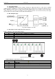
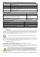
3. Operating status indication.
The PSU is equipped with LED indication of operation status. The presence of power at the outputs of the PSU
is indicated by the illumination of green LEDs on the front panel of the device.
3.1. LED indication
• LED1…LED8 green diodes indicate power at the outputs:
LB8- AUX1…AUX8.
In case of a power loss at the output (fuse activation), an appropriate diode goes out. (L1 for AUX1, L2 for AUX2
etc.)
4. Operation and use.
4.1 Overload or short circuit at the PSU output.
The AUX1 ÷ AUX8 PSU outputs of the LB8 strips are protected against a short circuit by glass fuses. If a fuse-
assisted protection has been chosen, replace the fuse (of the same parameters) in case of a failure.
4.2 Maintenance.
Any and all maintenance operations may be performed following the disconnection of the PSU from the power
supply network. The PSU does not require performing any specific maintenance measures. However, in case of
significant dust level, clean its interior with compressed air. In case of a fuse exchange, use the replacement of the same
parameters.
WEEE MARKING
According to the EU WEE Directive – It is required not to dispose of electric or electronic
waste as unsorted municipal waste and to collect such WEEE separately.
Pulsar
Siedlec 150, 32-744 Łapczyca, Poland
Tel. (+48) 14-610-19-40, Fax. (+48) 14-610-19-50
e-mail:
biuro@pulsar.pl, sales@pulsar.pl
http:// www.pulsar.pl, www.zasilacze.pl