
User Instructions
www.pulsar.pl PSDC08128
3
1. Technical description.
1.1 General description.
The PSDC08128 stabilized power supply is designed to supply HD cameras or other devices requiring
stabilized voltage of 12V DC. The output voltage adjustment range is adjusted via a potentiometer within the range
of 12V÷15V DC. The PSU features 8 outputs protected independently by either glass fuses or polymer fuse. A
failure (a short circuit) in the output circuit makes a fuse blow or an activation of the polymer fuse and
disconnection of the circuit from the DC power supply (+U). The PSU is housed in a metallic enclosure with an
indication panel featuring a microswitch indicating unwanted opening of the door (faceplate).
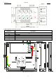
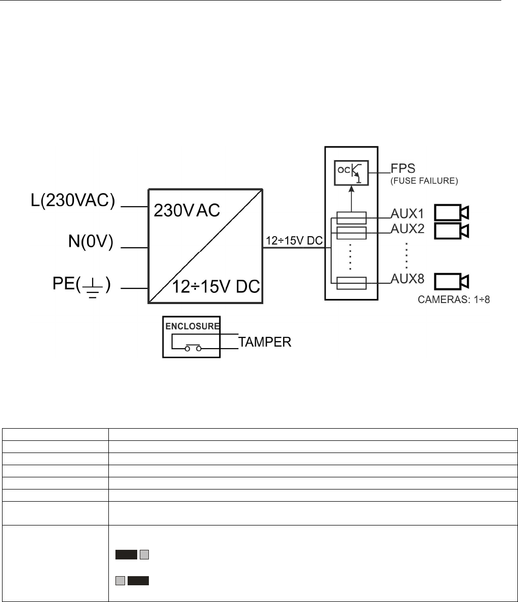
1.2. Block diagram (fig.1).
Fig.1. Block diagram of the PSU.
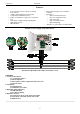
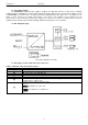
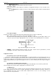
1.3. Description of PSU components and connectors.
Table 1. Elements of the PSU PCB (see fig. 2).
Element no.
Description
[1]
L1…
L8
(green) LEDs (indicating fuse activation)
[2]
F1…F8
glass fuses in AUX (+) circuits
[3]
IN
supply input of the LB8/AW strip
[4]
AUX1…
AUX8
outputs,
COM
(-) shared terminal
[5]
L
FPS
(red)
diode indicating failure of a particular output (fuse activation)
[6]
FPS
output indicating failure of a particular output, OC type
(normal status: L, failure: hi-Z)
[7]
Jumper for the selection of the fuse type:
Fx
Fx.x
Fx jumper on – glass fuse
Fx
Fx.x
Fx.x jumper off – polymer fuse