
User Instructions
www.pulsar.pl PSBOC351225
3
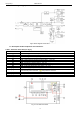
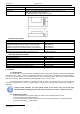
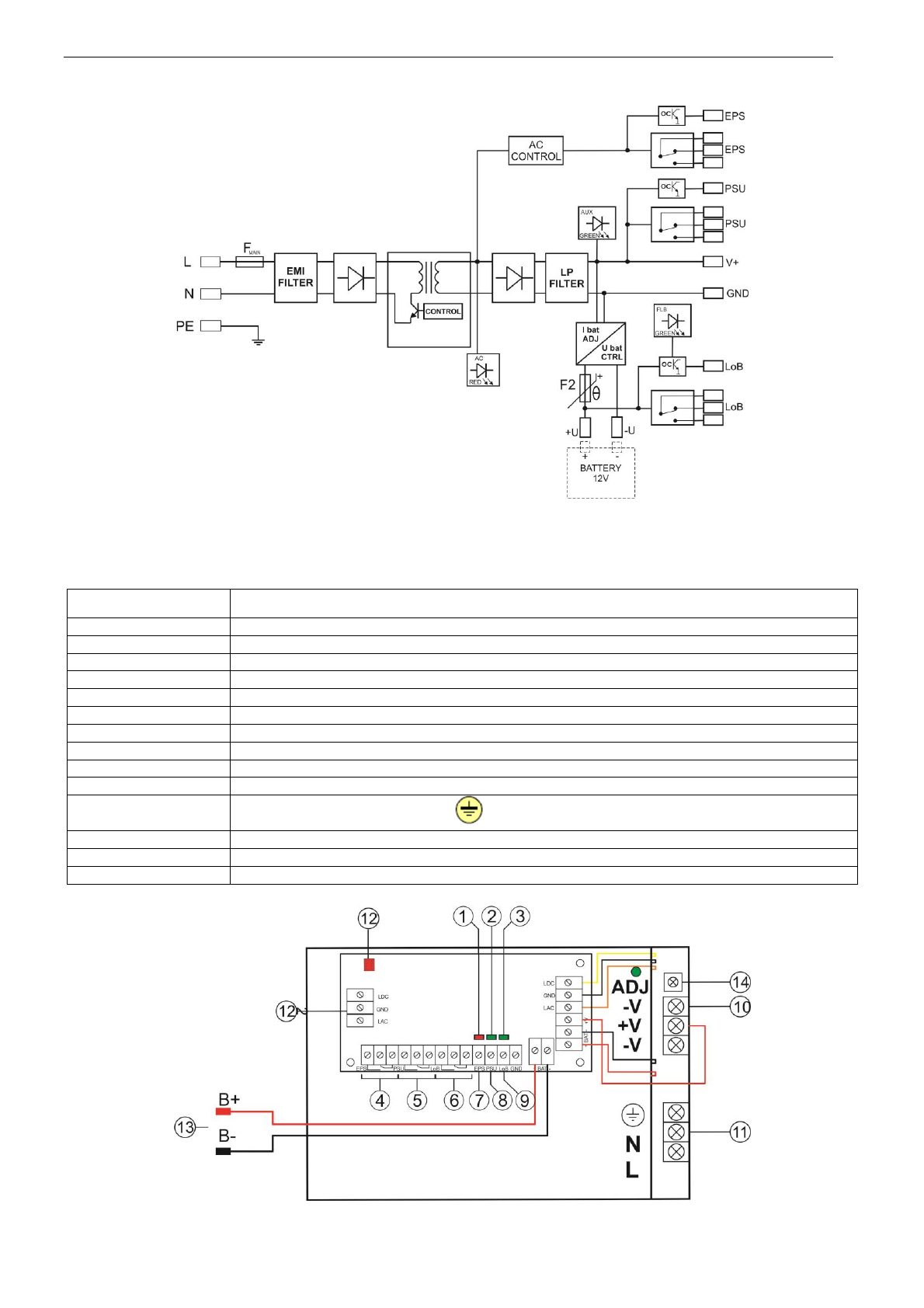
1.2. Block diagram. (fig.1).
Fig.1. Block diagram of the PSU.
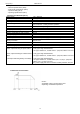
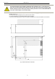
1.3. Description of PSU components and connectors.
Table 1. Elements of the PSU (see fig. 2).
Element no.
Description
[1]
LED indicating presence of AC power
[2]
LED indicating presence of DC power
[3]
LED indicating correct battery voltage
[4]
EPS - AC absence technical output – relay type
[5]
PSU - output indicating DC absence/PSU failure – relay type
[6]
LoB - output indicating battery low voltage – relay type
[7]
EPS - AC absence technical output – OC type
[8]
PSU - output indicating DC absence/PSU failure - OC type
[9]
LoB - output indicating battery low voltage - OC type
[10]
+V ,-V- DC supply output
[11]
L-N 230V/AC power connector, PE protection connector
[12]
Connector of extra LED indication
[13]
Battery connectors: +BAT =red, - BAT = black
[14]
V
ADJ
- potentiometer, DC voltage adjustment
Fig. 2. The view of the PSU.