
User Instructions

www.pulsar.pl PSBEN5024C/LCD BLACK POWER
8
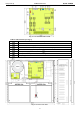
3.3 Description of PSU’s components and connectors.
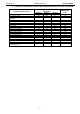
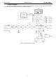
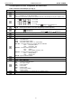
Table 1. Elements of the PSU pcb (see Fig. 2).
Element no
Description
PANEL – optical indication connector
P
BAT
– jumper; idle in this model
T
AC
– jumpers J1, J2; idle in this model
CAUTION. In this model, jumpers are operated from the LCD desktop’s level (see: chapter. 6.2).
I
BAT
– pin; battery charging current selection
J1= , J2= J3= I
BAT
=0,6 A
J1= , J2= J3= I
BAT
=1,5 A
J1= , J2= J3= I
BAT
=2,2 A
J1= , J2= , J3= I
BAT
=3 A
Caption: jumper on, jumper off
START – button (launching the PSU from a battery)
STOP – button (disconnection of the PSU during battery-assisted operation)
– pin; activation of the acoustic indication
- indication on
- indication off Caption: jumper on, jumper off
V
ADJ
– potentiometer, DC voltage adjustment
BUZZER – acoustic indicator
F
BAT
– fuse in the battery circuit
Connectors:
~AC~ – AC power input
+BAT – DC power battery output
+AUX – DC power output (+AUX= +U, -AUX=GND)
EPS FLT – technical output of AC network absence indication
open = AC power failure
close = AC power - O.K.
PSU FLT – technical output of PSU failure
open = failure
close = PSU working correctly - O.K.
APS FLT – technical output of battery failure
open = battery failure
close = battery O.K.
EXT IN – input of collective failure
V
EXT
pin – polarization of EXT IN circuit
Communication connector
LEDs – optical indication:
AC – presence of the AC power
AUX – DC output voltage
OVL – PSU overload
PSU – PSU failure
APS – battery failure
EXT – EXT IN input’s status
LB – battery charge
OVP – optical indication for activating the over voltage system
TAMPER – connector for the micro switch tamper