
User Instructions

3
4. Connect load/loads to proper output connectors of the power supply (positive end is marked as +V, negative as
-V).
5. Connect battery to the unit according marks (colors).
6. After the completion of tests and trial activation, close the housing, cabinet etc.
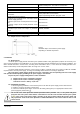
2.3. Description of terminals.
Elements/connectors
[Fig.1]
Description
L, N,
L-N - input voltage connectors 230V AC,
– protective conductor connector
-V
Power supply output (0V)
+V
Power supply output (+55V)
LED1
LED signals the presence of AC voltage
ADJ
Potentiometer - output voltage adjust
I1/I2
Jumper -battery charging current configuration:
Ibat =0,5 A
Ibat =1,0 A
Legend: jumper installed, jumper removed
B+
Battery terminal- positive (+)
Fig 1. Description of terminals.
B-
Battery terminal- negative (-)
Z1
Connector of optical signalization
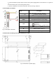
2.4. Dimensions and fitting of the PSB-1554828 power supply.
Fig. 2. Dimensions of power supply