
User Instructions

3
The circuit of the shock protection shall be performed with a particular care, i.e. the yellow and green
protection wire of the power cable shall be connected from one side to the terminal marked by the
symbol of in the casing of the power-supply. Operation of the power-supply without the properly
made and fully operational circuit of the shock protection is UNACCEPTABLE! It can result in failure
of devices and electric shock.
4. Connect load/loads to proper output connectors of the power supply (positive end is marked as +V,
negative as -V).
5. Connect battery to the unit according marks (colors).
6. After the completion of tests and trial activation, close the housing, cabinet etc.
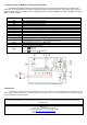
2.3. Description of terminals.
Elements/connectors
[Fig.1]
Description
L, N,
L-N - input voltage connectors 230 V AC,
– protective conductor connector
V-
Power supply output (0V)
V+
Power supply output (+13,8V)
LED1
LED signals the presence of AC voltage
ADJ
Potentiometer - output voltage adjust
I1/I2
Jumper -battery charging current configuration:
Ibat =1 A
Ibat =4 A
Legend: jumper installed, jumper
removed
B+
Battery terminal- positive (+)
Fig 1. Description of terminals.
B-
Battery terminal- negative (-)
Z1
Connector of optical signalization
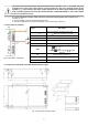
2.4. Dimensions and fitting of the PSB-15512110 power supply.
Fig. 2. Dimensions of power supply.