
User Instructions

2
Protection class electric shock protection
I (first) - requires a protective conductor
Connectors
I/O PCB: 0,5 – 2,5 mm
2
(AWG 26 – 12)
output of optical signalization: 4 pins micromatch socket
Additional accessories
Battery wires 6,3F – 45cm, ML062 angle muff (hole
5,2mm)
Electrical strength of insulation:
- between input (network) circuit and output circuits
of power-supply
- between input circuit and protection circuit
- between output circuit and protection circuit
2500 V AC min.
1500 V AC min.
500 V AC min.
Insulation resistance:
- between input circuit and output or protection
circuit
100 MΩ, 500 V DC
Storage temperature
-20ºC...+60ºC
Vibrations and impulse waves during transport
according to PN-83/T-42106
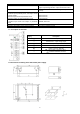
1.3. Description of terminals.
Elements/connectors
[Fig.1]
Description
[1]
LED for DC output voltage
[2]
Potentiometer - output voltage adjust
[3]
Connector of optical signalization LED
[4]
Power supply output (V+, V-)
[5]
Battery connector (B+, B-)
[6]
L-N – input voltage connectors 230 V,
– protective conductor connector
1.4. Dimensions and fitting of the PSB-12V3A power supply.