
Operating instructions

www.pulsar.pl POE084824B GREEN POWER CCTV PoE
8
3. Power supply operation indication.
3.1. Optical indication.
The PSU has 11 LED lights at the front panel:
RED LED:
• on – The PSU supplied with 230V AC voltage
• off – no 230V AC mains supply
RED LED:
• on – DC voltage at the output of the switch mode PSU
• off – no DC voltage at the output of the switch mode PSU
RED LED:
• on – fuse failure at one of the AUX1…AUX8 outputs
• off – no failure
GREEN LED:
• on – DC voltage at the AUX1…AUX8 output
• off – no DC voltage at the AUX1…AUX8 output
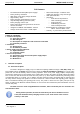
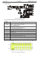
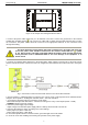
Additionally, the PSU is fitted with LED lights inside the enclosure – see Fig. 2 and 3:
- L
AC
red LED (Fig. 2, component 1) is permanently illuminated during normal operation (AC power ON).
No AC power is indicated by turning off the L
AC
LED.
- L
IN
green LED (Fig. 2, component 1) indicates DC voltage at the PoE module input. During normal operation (DC
supply) the LED is permanently illuminated. No DC no DC voltage at the module input is indicated by turning off the
L
IN
LED.
- L
FPS
red LED (Fig. 2, component 10) is not illuminated during normal operation (no failure). In case of activation of
the short circuit / overload protection at any output, the LED is permanently illuminated.
- L1 ÷ L8 green LEDs (Fig. 2, component 5) indicate voltage at the individual outputs of the module (L1 for AUX 1
etc.). Activation of the short circuit / overload protection of a given circuit is indicated by turning off one of the Lx
LEDs.
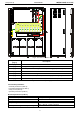
3.1. Technical outputs.
The PSU has the following indication outputs:
• FPS – technical output of the PSU status:
- OC type output indicating failure (short-circuit, overload). During normal operation, shorted to ground – L
state (0V). In case of power loss, the FPS technical output is switched into hi-Z state (high impedance) at least
at one of the AUX outputs.
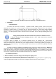
Fig. 6. Electrical diagram of the OC output.
- relay output. In case of failure, relay contacts are switched automatically.
Fig. 7. Electrical diagram of the relay output