
Operating instructions

www.pulsar.pl POE084824B GREEN POWER CCTV PoE
7
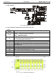
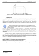
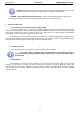
Figure 4. An example of mounting the Ethernet switch.
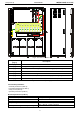
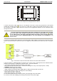
4. Connect the power cables (230V AC) to L-N terminals of the PSU. Connect the ground wire to the terminal
marked with grounding symbol: . Use a three-core cable (with a yellow and green PE protection wire) to make
the connection. The power cables should be connected to the appropriate terminals on the connection board
through the bushing.
The shock protection circuit shall be done with a particular care: the yellow and green wire
coat of the power cable should be connected to the terminal marked with the symbol
in the PSU enclosure. Operation of the PSU without the properly made and fully operational
shock protection circuit is UNACCEPTABLE! It can cause damage to the equipment or an
electric shock.
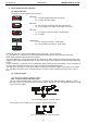
5. Connect the network cables (Ethernet) to the PoE module: supply voltage is present only at the AUX sockets
and the cameras should be connected to them. Pin assignment of the AUX and IN sockets is shown in the Figure
5:
Fig. 5. Connection of cameras and network devices to the IN and AUX terminals.
6. Use the F1/PTC1 ÷ F8/PTC8 jumpers to select the type of short circuit / overload protection of individual circuits.
Jumper in the Fx position – melting fuse activation, PTCx – PTC fuse activation.
7. If needed, the following technical connections can be made:
- FPS technical output of the PSU status – indicates the voltage loss at any of the outputs (AUX1 ÷ AUX8).
- TAMPER indicating enclosure opening.
8. Check the power supply output voltage:
- output voltage of the unloaded power supply without a battery should amount to U=54V DC.
9. Connect the batteries in series according to the color markings:
- battery output (+V): BAT+ cable/ red
- battery output (0V): BAT- cable / black
10. Check the optical indication of the PSU status: green LED light on the PoE module.
11. Close the cover after installing and checking the operation of the power supply.