
Operating instructions

www.pulsar.pl POE084824B GREEN POWER CCTV PoE
6
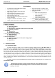
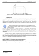
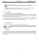
Diagram 1.
Maximum permissible output current depending on ambient temperature.
2. Installation.
2.1. Requirements.
The buffer PSU should be mounted by a qualified installer, holding relevant permits and licenses
(applicable and required for a given country) for 230V/AC and low-voltage installations. The unit should be
mounted in confined spaces, in accordance with the 2nd environmental class, with normal relative humidity
(RH=90% maximum, no condensation) and temperature range from -10°C up to +40°C. The power supply sh ould
operate in a vertical position in order to provide free and convectional air flow through ventilating holes of the
enclosure.
During normal operation, the total current drawn by the device should not exceed
I = 8x0,3A
*
. Maximum battery charging current is 0,2A. Total current of the receivers
+ battery is max 2,6A.
The power supply is designed for a continuous operation and is not equipped with a power-switch.
Therefore, an appropriate overload protection in the power supply circuit should be provided. Moreover, the user
should be informed how to disconnect the power supply unit from the mains supply (usually by assigning an
appropriate fuse in the fuse box). The electrical system shall be made in accordance with applicable standards
and regulations.
The PSU is designed for 10Mbit/s and 100Mbit/s Ethernet network (so-called Fast Ethernet). However, it
can not be used for a 1000 Mbit/s network (so-called Gigabit Ethernet). Connections between the power
supply and the camera can be done using UTP-3 cable (networks with data-rates up to 10 Mbit/s) or UTP-5 cable.
Due to the lower resistance wiring, it is recommended (especially at large distances between the power supply and
receivers) to use UTP-5 cable also for networks with data-rates up to 10 Mbit/s.
2.2. Installation procedure.
1. Before installation, cut off the voltage in the 230V power-supply circuit.
2. Mount the PSU in a selected location and lead the connecting cables.
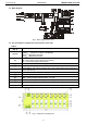
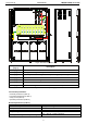
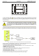
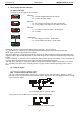
3. If required, mount the switch network (Ethernet Switch / Hub) on the mounting plate (element 6, Figure 3) using
cable ties supplied with the PSU. An example of mounting the Ethernet switch is shown in Figure 4:
*
See diagram 1