
Operating instructions

www.pulsar.pl POE084824B GREEN POWER CCTV PoE
3
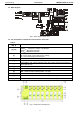
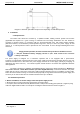
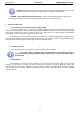
1.2. Block diagram.
Fig. 1. Block diagram of the PSU.
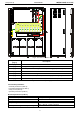
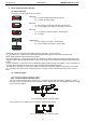
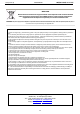
1.3. The description of components and connectors of the PSU.
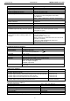
Table 1.
Component No.
[Fig. 2]
Description
[1], [10]
LED
optical indication
:
green L
IN
–
indication of voltage at the IN input
red L
AC
–
AC voltage indication
red L
FPS
–
FPS failure indication
[2]
Connector
:
IN –
power supply of the module (factory setting
)
AC – 230V
mains supply indication input
[3]
F1 ÷ F8
fuses in the
AUX1 ÷ AUX8 (+), F500mA circuits
[4]
Jumper to select melting fuse or PTC polymer fuse
[5]
Green LED L1 ÷ L8 -
voltage indication at the AUX outputs (during normal operation,
these LEDs are on)
[6] Network outputs (Ethernet + power supply) – for camera connection.
[7] Network outputs (Ethernet)
[8]
FPS –
technical output indicating failure – OC type
[9]
FPS –
technical output indicating failure – relay type
[11]
Optional, external optical indication connector (factory setting
)
[12] PE – grounding the shield of the RJ45 connectors (factory setting)
Table 1.
The description of components of the
PoE module.
Fig. 2. Components arrangement.