Model No. PGD95BiSCO 9500 Watt Dual Fuel Inverter Generator OPERATOR’S MANUAL Warning: The Engine Exhaust from this product contains chemicals known to the State of California to cause cancer, birth defects or other reproductive harm. STOP DO NOT RETURN TO STORE! HAVE QUESTIONS OR NEED SERVICE? 866-591-8921 support@pulsar-products.
Table of Contents Safety Warnings. . . . . . . . . . . . . . . . . . . . . . . . 1 Safety Instructions. . . . . . . . . . . . . . . . . . . . . . 2 CO Sentry. . . . . . . . . . . . . . . . . . . . . . . . . . . . . 4 Names of Components. . . . . . . . . . . . . . . . . . . 5 Control Panel . . . . . . . . . . . . . . . . . . . . . . . . . . 6 Specifications . . . . . . . . . . . . . . . . . . . . . . . . . 7 Preparation. . . . . . . . . . . . . . . . . . . . . . . . . . . . 8 Adding Engine Oil. . . . . . . .
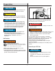
Safety Instructions Safety Precautions Before operating your generator, you must read and understand the manual and familiarize yourself with the safe operation practices. SYMBOL DESCRIPTION Safety Alert Symbol Electrocution Hazard Asphyxiation Hazard WARNING POISONOUS GAS HAZARD: Engine exhaust contains carbon monoxide, a poisonous gas that could kill you in minutes. You CAN NOT smell it, see it, or taste it. Even if you do not smell exhaust fumes, you could still be exposed to carbon monoxide gas.
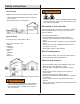
Safety Instructions WARNING Correct Usage Example location to reduce risk of carbon monoxide poisoning •ONLYuseoutsideanddownwind,farawayfromwindows, doors,andvents. •Directexhaustawayfromoccupiedspaces. Fuelanditsvaporsareextremelyflammableandexplosivewhich couldcauseburns,fire,orexplosionresultingindeathorserious injuryand/orpropertydamage.
Safety Instructions NOTE COSentry Improper treatment of the generator could damage it and shorten its life. TheCOSentrysystemwascreatedtoprotectfromdangerous carbonmonoxide.JustlikethedetectorforyourhometheCOSentry teststheairfordangerouslevelsofcarbonmonoxide.Ifdangerous levelsofcarbonmonoxidearedetectedthisgeneratorwill automaticallyshutoff. •Usegeneratoronlyforintendedapplications.
Components Before operating your generator, you must read and understand the manual and familiarize yourself with the safe operation practices.
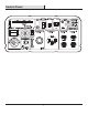
Control Panel CO SENTRY PROTECTION AGAINST CARBON MONOXIDE TO AVOID DAMAGE, DO NOT CONNECT OR DISCONNECT PARALLEL CABLES WHILE THE UNIT IS RUNNING.
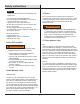
CONFIGURE GENERATOR ENGINE Specifications Engine Model 192F/P-2 Engine Type Single Cylinder, Four Stroke, Air Cooled, Overhead Valve, Gasoline Engine, Cylinder Inclined 25° Cylinder Bore x Stroke(mm) 92x69 Displacement 458cc Compression Ratio 8.5:1 Gas Distribution Mode OHV Cooling Mode Forced Cold Air Output Power (kW/r/min) 10.5/3600 Starting Mode Electric and Manual Recoil Gasoline Tank Capacity 6.5 gallons Fuel Unleaded Gasoline or LPG (Propane) Engine Oil Capacity(L) 1.
Preparation Preperation Your generator requires some assembly. This unit ships from our factory without oil; it must be properly filled with oil before operation. Unpacking 1. Set the shipping carton on a solid, flat surface. 2. Remove everything from the carton except the generator. 3. Using the carrying handles of the unit, carefully remove the generator from the box (two people lifting is recommended). 3. Remove oil fill cap/dipstick to add oil. 4.
Preparation NOTICE Check oil level often during the break-in period. Refer to the Maintenance section for recommended service intervals. CAUTION This engine is equipped with a low oil shut-off and will stop when the oil level in the crankcase falls below a critical level. NOTICE 4. Replace the fuel cap and wipe up any spilled gasoline with a dry cloth then remove the cloth from the area. The first 5 hours of run time are the break-in period for the unit.
Preparation 6. Remove the safety plug or cap from the propane tank valve and attach the other end of the hose to the LPG connector on the tank. Hand-tighten. 7. Turn the propane tank valve to the fully open position. Check all connections for leaks by wetting the fittings with a solution of soap and water. Bubbles which appear or bubbles which grow indicate that a leak exists. If a leak exists at a fitting, turn the propane tank valve to the fully closed position and tighten the fitting.
Preparation 3. A quick-connect battery plug is pre-installed on the battery. Remove the cable tie securing the plugs, align colors, then push firmly to connect them. 4. Align the tabs on the bottom of the battery access cover with the generator case then push to reinstall the cover. Note: The generator is equipped with a battery charging feature. Once the engine is running, a small current will slowly recharge the battery.
Operation Generator Location Starting The Generator WARNING 1. Make sure the generator is on a solid, flat, level surface. 2. Disconnect all electrical loads from the generator. Never start or stop the generator with electrical devices plugged in or turned on. 3. Turn the fuel switch to desired fuel source. When the Switch is in the Gasoline position, the generator is ready to start with Gasoline. When the Switch is in the LPG position, the generator is ready to start with propane.
Operation DANGER 6. Choose the starting method Recoil Start: Firmly grasp and pull the recoil handle slowly until you feel resistance, let it retract then pull swiftly. Fire and explosion hazard. Always turn the propane tank valve to the fully closed position if not running the generator on propane. WARNING When using the generator with propane, make sure there is no possible ignition source close to the generator. Gasoline To LPG IMPORTANT: Load capacity is reduced when running on LPG.
Operation Stop The Engine 2. If the OVERLOAD light turns on and the generator stops producing power, it has been overloaded. 3. Turn off and disconnect all electrical devices and stop the engine. Compare device requirements to generator rating and reduce the total wattage of connected devices if necessary. Move anything that may be limiting generator ventilation away. 4. Check if any circuit breakers have tripped and make sure that ALL circuit breakers are reset before starting the generator again. 5.
Operation Generator Capacity NOTICE Do not overload the generator's capacity. Exceeding your generator's wattage capacity can damage the generator and/or electrical devices connected to it. Make sure the generator can supply enough continuous (running) and surge (starting) watts for the items you will power at the same time. The total power requirements (Volts x Amps=Watts) of all appliances connected must be considered.
Maintenance WARNING ACCIDENTAL STARTING: Turn the fuel selector to the “OFF” position, wait for the engine to cool, and disconnect the spark plug cable before performing any inspection, maintenance, or cleaning procedures. EQUIPMENT FAILURE: Do not use damaged equipment. If abnormal noise, vibration, or excess smoking occurs, have the problem corrected before further use. Many maintenance procedures, including any not detailed in this manual, will need to be performed by a qualified technician for safety.
Maintenance Checking and Filling Fuel WARNING TO PREVENT SERIOUS INJURY FROM FIRE: Fill the fuel tank in a well-ventilated area away from ignition sources. If the engine is hot from use, shut the engine off and wait for it to cool before adding fuel. Do not smoke. 1. Clean the Fuel Cap and the area around it. 2. Unscrew and remove the Fuel Cap. 3. Remove the strainer and remove any dirt and debris. Then replace the strainer. 3. Remove the lower Rubber Seal from underneath the generator.
Maintenance Air Filter Element Maintenance 1. Allow the generator to cool completely. 2. Remove the Screws from the back of the generator. 3. Remove the Tail Pipe and Spark Arrestor. 4. Clean the Spark Arrestor using a wire brush (sold separately). Replace the arrestor if damaged. 1. Loosen screws and remove the Air Filter Access Panel on the left side of the generator.
Maintenance Draining the Carburetor NOTICE UseonlyBPR6ES(NGK)typesparkplugorequivalent.Using an incorrect spark plug may damage the engine. AfterclosingtheFuelValve,placeanappropriatecontainerunder the Carburetor and carefully remove the Drain Bolt from the bottom of the Carburetor Bowl, allowing the fuel to drain completely. Replace the Drain Bolt after draining. 5. When installing a new spark plug, adjust the plug's gap to the specification on the Specifications Chart.
Troubleshooting Problem Possible Causes Probable Solutions THE ENGINE WILL NOT START FUEL RELATED: FUEL RELATED: 1. No fuel in tank or fuel valve closed. 1. Fill fuel tank with fresh 87+octane stabilizer-treated unleaded gasoline and open fuel valve. Do not use gasoline with more than 10% ethanol (E15,E20,E85, etc.). 2. Choke not in START position, cold engine. 2. Move Choke to START position. 3. Gasoline with more than 10% ethanol used. 3.
Troubleshooting Problem Possible Causes Probable Solutions THE ENGINE WILL NOT START COMPRESSION RELATED: COMPRESSION RELATED: 1. Cylinder not lubricated. 1. Pour a tablespoon of oil into the spark plug Problem after long storage periods. hole. Crank the engine a few times and try to start again. 2. Loose or broken spark plug. 2. Tighten spark plug. (Hissing noise will occur when trying to start.) If that does not work, replace the spark plug.
Troubleshooting Problem Possible Causes Probable Solutions ENGINE STOPS SUDDENLY 2. Fuel tank empty or full of impure or low-quality 2. Fill fuel tank with fresh 87+ octane stabilizer gasoline. treated unleaded gasoline. Do not use gasoline with more than 10% ethanol(E15, E20,E85,etc.). 3. Defective fuel tank cap creates a vacuum and 3. Test/replace fuel tank cap. prevents proper fuel flow. 4. Faulty magneto. 4. Have qualified technician service magneto. 5.