R Model: PG5000BiSRCO 5000 Watt Dual Fuel Inverter Generator OPERATOR’S MANUAL Warning: The Engine Exhaust from this product contains chemicals known to the State of California to cause cancer, birth defects or other reproductive harm. STOP DO NOT RETURN TO STORE! HAVE QUESTIONS OR NEED SERVICE? 866-591-8921 support@pulsar-products.
Table of Contents Safety Warnings. . . . . . . . . . . . . . . . . . . . . . . . 1 Safety Instructions. . . . . . . . . . . . . . . . . . . . . . 2 CO Sentry. . . . . . . . . . . . . . . . . . . . . . . . . . . . . 4 Names of Components. . . . . . . . . . . . . . . . . . . 5 Control Panel . . . . . . . . . . . . . . . . . . . . . . . . . . 6 Specifications . . . . . . . . . . . . . . . . . . . . . . . . . 7 Preparation. . . . . . . . . . . . . . . . . . . . . . . . . . . . 8 Adding Engine Oil. . . . . . . .
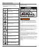
Safety Instructions Safety Precautions Before operating your generator, you must read and understand the manual and familiarize yourself with the safe operation practices. SYMBOL DESCRIPTION Safety Alert Symbol Electrocution Hazard Asphyxiation Hazard WARNING POISONOUS GAS HAZARD: Engine exhaust contains carbon monoxide, a poisonous gas that could kill you in minutes. You CAN NOT smell it, see it, or taste it. Even if you do not smell exhaust fumes, you could still be exposed to carbon monoxide gas.
Safety Instructions WARNING Correct Usage Example location to reduce risk of carbon monoxide poisoning • ONLY use outside and downwind, far away from windows, doors, and vents. • Direct exhaust away from occupied spaces. Fuel and its vapors are extremely flammable and explosive which could cause burns, fire, or explosion resulting in death or serious injury and/or property damage.
Safety Instructions NOTE CO Sentry Improper treatment of the generator could damage it and shorten its life. The CO Sentry system was created to protect from dangerous carbon monoxide. Just like the detector for your home the CO Sentry tests the air for dangerous levels of carbon monoxide. If dangerous levels of carbon monoxide are detected this generator will automatically shut off. • Use generator only for intended applications.
Components Before operating your generator, you must read and understand the manual and familiarize yourself with the safe operation practices. 1 4 9 7 6 5 8 2 10 3 7. Control Panel: The control panel contains the outlets and operational controls. 8. Spark Plug Cover: Spark plug can be maintained after removing this cover. 9. Left Side Panel: Battery and quick connection plug can be accessed by removing this panel. 10.
Control Panel 10 19 8 14 12 6 7 4 13 15 11 9 18 1 5 17 3 16 1. 120 Volt AC, 20 Amp Duplex NEMA 5-20R Receptacle: The receptacle can supply a maximum of 20 Amps. 2. Ground Terminal: The ground terminal is used to externally ground the generator. 3. Parallel Connectors: A compatible Pulsar Inverter Generator can be connected for additional power output. 4. LED Switch: Light the panel up when the LED Switch is turned on. 5. USB Ports: USB TypeA 5V/3.6A, 9V/2.5A, 12V/2A and USB Type C. 6.
Specifications Model PG5000BiSRCO Engine Type Single Cylinder, Four Stroke, Air Cooled Gasoline Engine Displacement 192cc Rated Power (kW) Gasoline 4 Peak Power (kW) Gasoline 5.0 Rated Power (kW) LPG/Propane 3.6 Peak Power (kW) LPG/Propane 4.
Preparation Preperation Your generator requires some assembly. This unit ships from our factory without oil; it must be properly filled with oil before operation. Unpacking 1. Set the shipping carton on a solid, flat surface. 2. Remove everything from the carton except the generator. 3. Using the carrying handles of the unit, carefully remove the generator from the box (two people lifting is recommended). 3. Remove oil fill cap/dipstick to add oil. 4.
Preparation NOTICE 4. Replace the fuel cap and wipe up any spilled gasoline with a dry cloth then remove the cloth from the area. DANGER Check oil level often during the break-in period. Refer to the Maintenance section for recommended service intervals. CAUTION Do not overfill the gasoline the tank. Overfilling can result in a fire, explosion,or death. WARNING This engine is equipped with a low oil shut-off and will stop when the oil level in the crankcase falls below a critical level.
Preparation NOTICE 6. Remove the safety plug or cap from the propane tank valve and attach the other end of the hose to the LPG connector on the tank. Hand-tighten. 7. Turn the propane tank valve to the fully open position. Check all connections for leaks by wetting the fittings with a solution of soap and water. Bubbles which appear or bubbles which grow indicate that a leak exists. If a leak exists at a fitting, turn the propane tank valve to the fully closed position and tighten the fitting.
Preparation Grounding The Generator Attach grounding wire (if required by code) • Ground the generator by tightening the grounding nut against a grounding wire. • Connect the other end to a copper or brass grounding rod that’s driven into the earth. A generally acceptable grounding wire is a No. 12 AWG (American Wire Gauge) stranded copper wire. Grounding codes can vary by location. Please contact a local electrician to check the grounding regulations for your area.
Operation Generator Location Starting The Generator WARNING 1. Make sure the generator is on a solid, flat, level surface. 2. Disconnect all electrical loads from the generator. Never start or stop the generator with electrical devices plugged in or turned on. 3. Turn the fuel switch to desired fuel source. When the switch is in the gas position, the generator is ready to start with gasoline. When the switch is in the LPG position, the generator is ready to start with propane.
Operation DANGER 6. For Recoil Start Recoil Start: Firmly grasp and pull the recoil handle slowly until you feel resistance, let it retract then pull swiftly. If it fails to start successfully, wait for 3 seconds then repeat this step. Fire and explosion hazard. Always turn the propane tank valve to the fully closed position if not running the generator on propane. WARNING When using the generator with propane, make sure there is no possible ignition source close to the generator.
Operation Stop The Engine 2. If the OVERLOAD light turns on and the generator stops producing power, it has been overloaded. 3. Turn off and disconnect all electrical devices and stop the engine. Compare device requirements to generator rating and reduce the total wattage of connected devices if necessary. Move anything that may be limiting generator ventilation away. 4. Check if any circuit breakers have tripped and make sure that ALL circuit breakers are reset before starting the generator again. 5.
Operation High Altitude Operation At high altitude, the standard carburetor air/fuel mixture will be too rich. Performance will decrease, and fuel consumption will increase. A very rich mixture will also foul the spark plug and cause hard starting. Operation at an altitude that differs from that at which this engine was certified, for extended periods of time, may increase emissions. High altitude performance can be improved by specific modifications to the carburetor.
Maintenance WARNING Turn the generator “OFF”, wait for the engine to cool, and disconnect the spark plug cable before performing any inspection, maintenance, or cleaning procedures. EQUIPMENT FAILURE: Do not use damaged equipment. If abnormal noise, vibration, or excess smoking occurs, have the problem corrected before further use. Many maintenance procedures, including any not detailed in this manual, will need to be performed by a qualified technician for safety.
Maintenance Checking and Filling Fuel WARNING TO PREVENT SERIOUS INJURY FROM FIRE: Fill the fuel tank in a well-ventilated area away from ignition sources. If the engine is hot from use, shut the engine off and wait for it to cool before adding fuel. Do not smoke. 1. Clean the Fuel Cap and the area around it. 2. Unscrew and remove the Fuel Cap. 3. Remove the strainer and remove any dirt and debris. Then replace the strainer. Note: Do not use gasoline containing more than 10% ethanol (E10).
Maintenance Air Filter Element Maintenance 1. Allow the generator to cool completely. 2. Remove the Screws from the back of the generator. 3. Remove the Tail Pipe and Spark Arrestor. 4. Clean the Spark Arrestor using a wire brush (sold separately). Replace the arrestor if damaged. 1. Loosen screws and remove the Air Filter Access Panel on the right side of the generator.
Maintenance NOTICE Draining the Carburetor Use only BPR6ES (NGK) type spark plug or equivalent. Using an incorrect spark plug may damage the engine. Shut off gasoline flow by moving the fuel selector to LPG, place an appropriate container under the carburetor and carefully remove the drain bolt from the bottom of the carburetor bowl, allowing the fuel to drain completely. Replace the drain bolt after draining. 5.
Troubleshooting Problem Engine is running, but AC output is not available Cause 1. Open circuit breaker 2. Poor connection 3. Defective cord set 4. Connected device is faulty 5. Fault in generator Engine runs well without load but bogs 1. Short circuit in connected device down when loads are connected 2. Generator is overloaded LED light 3. Clogged fuel filter 4. Engine speed is too slow 5. Short circuit in generator Solution 1. Reset circuit breaker 2. Check and repair 3. Check and repair 4.