
User Instructions


www.pulsar.pl MSRK2012
3
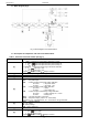
1.2. Block diagram (fig.1)
Fig.1. Block diagram of the PSU module.
1.3. Description of components and connectors PSU module.
Table 1. Elements of the PSU module pcb (fig. 2).
Element no.
Description
[1]
P
BAT
; pins - configuration of UVP battery protection function
P
BAT
= protection (disconnection) of the battery off
P
BAT
= protection (disconnection) of the battery on
T
AC
; pins T
AC
- configuration of time lag of AC failure indication
T
AC
= time lag T= 60s
T
AC
= time lag T= 10s
Legend: jumper installed jumper removed
[2]
START button (launching from battery)
[3]
V
ADJ
potentiometer, DC 12 ÷ 14,5V adjustment
[4]
F
BAT
fuse in the battery circuit, F3,15A / 250V
[5]
Terminals:
~AC~ – AC power input
EPS – technical output of AC power failure indication
hi-Z state = AC power failure
0V state = AC power - O.K.
PSU – technical output of PSU failure indication
hi-Z state = failure
0V state = PSU status O.K.
LoB – technical output of low battery voltage indication
hi-Z state = battery voltage U
BAT
<11,5V
0V state = battery O.K.
+BAT- – terminals for battery connection
+AUX- – DC power output, (+AUX= +U, -AUX=GND)
Description: hi-Z – high impedance, 0V – connection to the ground GND
[6]
LEDs – optical indication:
AC - AC voltage
LB - battery charge
AUX - output voltage DC
[7]
Connector to the external LED indicators.
[8]
I
BAT
jumper;– battery charging current selection
I
BAT
= Ibat =0,2A
I
BAT
= Ibat =0,5A
Legend: jumper installed jumper removed