
Data Sheet


Interface
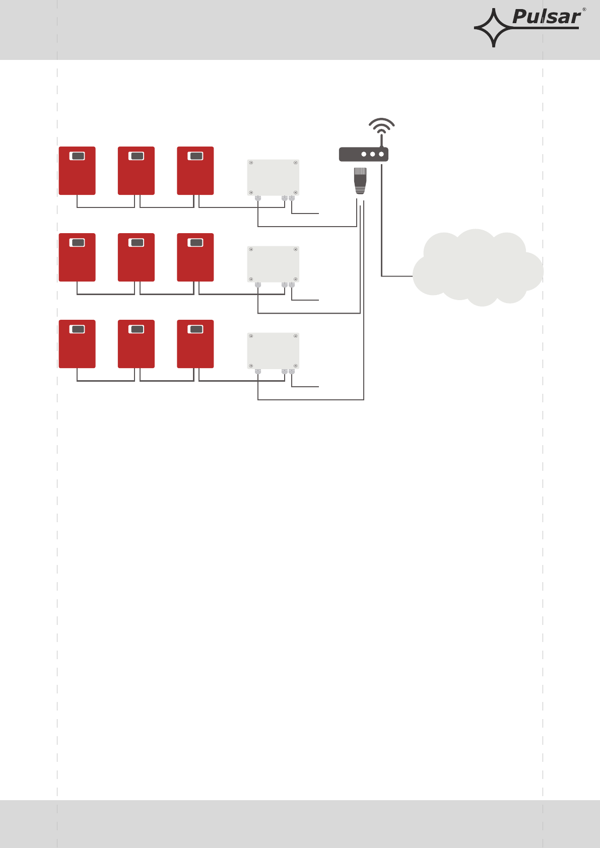
Schematic diagram of Ethernet network communication
The network topology is based on an Ethernet switch (e.g. switch, router) to which subsequent
segments of power supplies are connected (connected in the RS485 bus) via the RS485-Ethernet interface.
Each interface has a static IP address. The communication between a PC and an end PSU is effected through
entering of the IP address of the interface, the address of the PSU in the RS485 bus, and the number of the port in
which the communication takes place. An interface may support a maximum of 247 PSUs on one RS485 bus.
10 - 30VDC
statyczny adres IP
statyczny adres IP
statyczny adres IP
ETHERNET
ROUTER WiFi
10 - 30VDC
ETHERNET
ETHERNET
10 - 30VDC
ETHERNET
RS485 bus, max 1200m
RS485 bus, max 1200m
RS485 bus, max 1200m
EN54C/LCD + INTR/C EN54C/LCD + INTR/C EN54C/LCD + INTR/C
EN54C/LCD + INTR/C EN54C/LCD + INTR/C EN54C/LCD + INTR/C
EN54C/LCD + INTR/C EN54C/LCD + INTR/C EN54C/LCD + INTR/C
Interfejs
RS485 - ETHERNET
„INTRE”
Interfejs
RS485 - ETHERNET
„INTRE”
Interfejs
RS485 - ETHERNET
„INTRE”
Tel. +48-14-610-19-40, fax: +48-14- 610-19-50, www.pulsar.pl, e-mail: sales@pulsar.pl