
Operating instructions

2
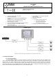
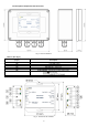
1.2 Description components and connectors.
Fig. 1. View of enclosure.
Table 1. (See fig. 2)
Element no.
(Fig. 2)
Description
[1]
The PoE IN-input port
[2]
LED LAN (yellow)
[3]
LED PoE (green)
[4]
PoE OUT 1/2 - output ports
[5]
PoE OUT 3 – output port (passive)
[6]
Power ON/OFF – PoE OUT1 /2 power supply jumper
[7]
The choice between the IEEE 802.3 af/at standard
Fig. 2. The view of the extender.