
User Instructions

www.pulsar.pl EN54C RED POWER plus
9
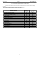
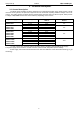
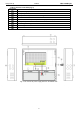
Table 2. Elements of the PSU (Fig. 3).
Component
No.
Description
PSU (tab. 1, Fig. 2)
Battery temperature sensor
Battery connectors; positive: +BAT = red, negative: - BAT = black
Place to install the EN54C-LB4 or EN54C-LB8 fuse module
TAMPER; microswitch (contacts) of antisabotage protection (NC)
Fitting battery
Embossing for cable gland
Embossings for concealed wires
Lock
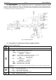
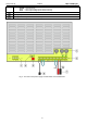
Fig. 3. The view of the power supply based on the EN54C-2A7.