
User Instructions

www.pulsar.pl EN54C RED POWER plus
7
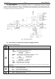
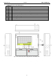
3.2. Block diagram.
The power supplies has been manufactured based on a high-efficiency system of AC/DC
converter. Applied microprocessor circuit is responsible for the full diagnostics of the PSU parameters and
batteries. The figure below shows a flowchart of the power supply, along with selected functional blocks which
are essential for the proper functioning of the unit.
Fig. 1. PSU block diagram.
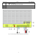
3.3. Description of components and power supply terminals.
Table 1. Elements of the PSU (Fig. 2).
Compone
nt No.
Description
L-N-PE 230 V power connector with protective terminal
Terminals:
TEMP – input of the battery temperature sensor
TAMPER – input of the microswitch tamper
Closed input = no indication
Open input = alarm
ALARM – technical output of collective failure of the PSU - relay type
EPS – technical output of AC power failure indication
open = AC power failure
closed = AC power - O.K.
EXTi – external failure input
Closed input = no indication
Open input = alarm
+BAT- – terminals for connecting the battery
+AUX1- – AUX1 power output ( - AUX=GND)
+AUX2- – AUX2 power output ( - AUX=GND)
CAUTION! In Fig.2 the set of contacts shows a potential-free status of the relay, which corresponds to power
supply failure.
Fuses:
F
BAT
– fuse in the battery circuit,
F
AUX1
– fuse in the AUX1 output circuit,
F
AUX2
– fuse in the AUX2 output circuit,
The fuse values are given in table 4 - "Electrical parameters".
LEDs – optical indication:
230 V – voltage in the 230 V circuit