
User Instructions


www.pulsar.pl EN54C RED POWER plus
21
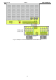
Short-circuit protection SCP
F4 A
F5 A
F6,3 A
F10 A
- F
AUX1
, F
AUX2
melting fuse (failure requires fuse replacement)
Overload protection OLP
105-150% of power supply, automatic recovery
Battery circuit protection SCP and reverse
polarity connection
F5 A
F6,3 A
F10 A
F12,5 A
- F
BAT
melting fuse (failure requires fuse replacement)
Deep discharge battery protection UVP
U<20 V (± 2%) – disconnection of the batteries
Tamper indicating enclosure opening
Microswitch TAMPER
Technical outputs:
- EPS FLT; indicating AC power failure
- ALARM; indicating collective failure
- relay type: 1 A@ 30 V DC /50 V AC
- 10s time lag.
- relay type: 1 A@ 30 V DC /50 V AC
Technical inputs:
- EXTi; external failure input
- TAMPER; input of the microswitch tamper
Closed input – no indication
Open input - alarm
Closed input – no indication
Open input - alarm
Optical indication:
- LEDs on the PCB of the power supply unit (see section 3.3)
- LED panel
~230 V mains power supply ON
DC power at the AUX outputs
failure indication
Fuses: - F
BAT
- F
AUX1
- F
AUX2
F 5 A/250 V
F 4 A/250 V
F 4 A/250 V
F 6,3 A/250 V
F 5 A/250 V
F 5 A/250 V
F 10 A/250 V
F 6,3 A/250 V
F 6,3 A/250 V
F 12,5 A/250 V
F 10 A/250 V
F 10 A/250 V
Additional equipment
(not included)
- fuse modules: EN54C-LB4, EN54C-LB8
- sequential modules: EN54C-LS4, EN54C-LS8