
User Instructions


www.pulsar.pl EN54C RED POWER plus
13
5. Functions
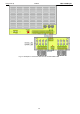
5.1. Control Panel.
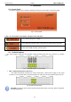
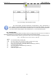
The PSU is equipped with a LED panel allowing checking the current status of the power supply.
Fig. 6. Control panel.
Table 3. The description of the buttons and LEDs of the LCD panel.
- green LED indicating 230 V voltage
- green LED AUX indicating power at the AUX1 and AUX2 output of the PSU
- yellow LED ALARM indicating collective failure
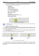
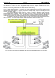
5.2. Technical outputs.
The power supply is fitted with relay indication outputs changing state upon the occurrence of a specific
event.
Fig. 7. Electrical diagram of relay outputs.
EPS - output indicating 230 V power loss.
The output indicates 230 V power loss. Under normal status – with the 230 V supply on, the output
is closed. In case of power failure, the PSU will switch the output into the open position after a time 10s.
Fig. 8. EPS technical output.
CAUTION! In Figure the set of contacts shows a potential-free status of the relay, which corresponds
to power supply failure.