
Modbus Protocol

Strona
5
z
10
1 – active
F70 – Default settings 3115: 10 1-bit
0 – inactive
1 – active
F71 – Low LCD battery
voltage
3115: 11 1-bit
0 – inactive
1 – active
F73 – Default settings 3115: 12 1-bit
0 – inactive
1 – active
F74 – Default settings 3115: 13 1-bit
0 – inactive
1 – active
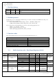
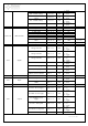
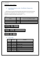
3116-3123 Measurements
Voltage Uout 3116: 15…0 uint16_t mV
Voltage Aux1 3117: 15…0 uint16_t mV
Voltage Aux2 3118: 15…0 uint16_t mV
Battery voltage Ubat 3119: 15…0 uint16_t mV
Charging current Ild 3120: 15…0 uint16_t mA
Battery current Ibat 3121: 15…0 uint16_t mA
Battery circuit resistance
Rbat
3122: 15…0 int16_t mΩ
-1: none
Battery temperature Tbat 3123: 15…0 int16_t ˚C
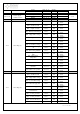
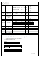
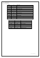
3124 Signals
Charge level 30% 3124: 1…0 2-bit
0 – off
1 – on
2 – toggle
Charge level 60% 3124: 3…2 2-bit
0 – off
1 – on
2 – toggle
Charge level 90% 3124: 5…4 2-bit
0 – off
1 – on
2 – toggle
AC state 3124: 6 1-bit
0 – inactive
1 – active
Battery charging 3124: 7 1-bit
0 – inactive
1 – active
Battery test in progress 3124: 8 1-bit
0 – inactive
1 – active
Battery test is forbidden 3124: 9 1-bit
0 – inactive
1 – active
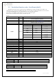
3125 Inputs
Tamper 3125: 0 1-bit
0 – inactive
1 – active
EXTi 3125: 1 1-bit
0 – inactive
1 – active
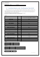
3126 Outputs
Led AC – Power supply 3126: 1…0 2-bit
0 – off
1 – on
2 – toggle
Led APS – Power supply 3126: 3…2 2-bit
0 – off
1 – on
2 – toggle
Led ALARM – Power
supply
3126: 5…4 2-bit
0 – off
1 – on
2 – toggle
Led AC – LCD panel 3126: 7…6 2-bit
0 – off
1 – on
2 – toggle
Led AUX1 – LCD panel 3126: 9…8 2-bit
0 – off
1 – on
2 – toggle
Led AUX2 – LCD panel 3126: 11…10 2-bit 0 – off