EN54-5A40 v.1.1 EN54 27,6V/5A/2x40Ah power supply unit for fire alarm systems EN** Edition: 8 from 19.01.2021 Supersedes the edition: 7 from 05.02.
www.pulsar.pl RED POWER EN54-5A40 TABLE OF CONTENTS 1. PSU FEATURES: .................................................................................................................................... 4 2. PACKAGE CONTENTS. ....................................................................................................................... 5 3. FUNCTIONAL REQUIREMENTS OF THE PSU. ............................................................................. 6 4. TECHNICAL DESCRIPTION. .................
www.pulsar.pl EN54-5A40 RED POWER 7. RESERVE POWER SUPPLY CIRCUIT. .......................................................................................... 30 7.1. BATTERY DETECTION. ........................................................................................................................................................ 30 7.2. PROTECTION AGAINST SHORT-CIRCUIT OF THE BATTERY TERMINALS................................................................................. 30 7.3.
www.pulsar.pl EN54-5A40 RED POWER 1.
www.pulsar.pl EN54-5A40 2. Package contents.
www.pulsar.pl RED POWER EN54-5A40 3. Functional requirements of the PSU. The buffer power supply for fire alarm systems has been designed in accordance with the following standards: - EN 54-4:2001 and / A2:2007 Fire detection and fire alarm systems. - EN 12101-10:2007 Smoke and heat control systems.
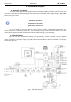
www.pulsar.pl EN54-5A40 RED POWER 4. Technical description. 4.1. General description. The buffer power supply has been designed for an uninterrupted supply of fire alarm systems, smoke and heat control systems, fire protection equipment and fire automatics requiring stabilized voltage of 24 V DC (± 15%).
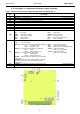
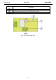
www.pulsar.pl RED POWER EN54-5A40 4.3. Description of components and power supply terminals. Table 1. Components of the Power supply PCB (Printed Circuit Board) (Fig. 2). Component No.
www.pulsar.pl RED POWER EN54-5A40 Table 2. Components of the PCB of the EMC filter (Fig. 3). Component Description No. FMAINS fuse in the power supply circuit 230 V, T6,3 A / 250 V L-N power supply connector 230 V, Connector– for connecting the PSU. protective connector Fig. 3. The view of the EMC filter.
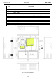
www.pulsar.pl EN54-5A40 Table 3. Elements of the PSU (Fig. 4). Component Description No. [1] Isolation transformer [2] Printed Circuit Board (see Table 1, Fig. 2) [3] Battery temperature sensor. Space to install an additional module: [4] “INTR”, “INTE” [5] Place to install the EN54-LB4 or EN54-LB8 fuse module [6] TAMPER; microswitch (contacts) of antisabotage protection (NC) [7] EMC filter module (see Table 2, Fig.
www.pulsar.pl EN54-5A40 RED POWER 5. Installation. 5.1. Requirements. The PSU is to be mounted by a qualified installer, holding relevant permits and licenses (applicable and required for a given country) for ~230 V in and low-voltage installations. As the power supply is designed for a continuous operation and is not equipped with a powerswitch, therefore, an appropriate overload protection in the power supply circuit should be provided.
www.pulsar.pl RED POWER EN54-5A40 5.2. Installation procedure. CAUTION! Before installation, cut off the voltage in the 230 V power-supply circuit. To switch power off, use an external switch, in which the distance between the contacts of all poles in the disconnection state is not less than 3mm It is required to install an installation switch with a nominal current of min. 3A in the power supply circuits outside the power supply unit. 1.
www.pulsar.pl EN54-5A40 RED POWER 6. Functions. 6.1. Control Panel. The PSU features a panel with buttons and LED display, enabling reading of all the available electrical parameters. The panel buttons are used to select and confirm the parameters, which should be displayed. Fig. 7. Control panel. Table 6. The description of the buttons and LEDs of the LED panel.
www.pulsar.pl RED POWER EN54-5A40 6.2. Main menu. The PSU is equipped with a menu, which allows to preview the current electrical parameters. Diagram explaining the menu structure is presented below. Fig. 8. Menu of the display. Table 7. The description of display symbols.
www.pulsar.pl EN54-5A40 RED POWER 6.2.1. Voltage indicator „Uo1”, „Uo2” Voltage indicator displays the measured output voltage at the AUX1 and AUX2 outputs. If the voltage drops below 26 V or exceeds 29.2 V, the PSU will indicate a failure. The resolution of voltage measurement is 0.1 V and should be treated with caution. If a greater accuracy is required, use a multimeter. 6.2.2.
www.pulsar.pl EN54-5A40 RED POWER - press „OK” button - number 1, indicating the number of failure in the memory (the highest priority), will be displayed. Then, after one second, failure code will be displayed automatically - press „OK” button - the number 2, denoting the next number of failure in the memory, will be displayed.
www.pulsar.pl RED POWER EN54-5A40 - press „OK” button - the number 2, denoting the next number of failure in the memory, will be displayed. Then, after one second, the next failure code will be displayed automatically - if the memory has more failures, pressing the "OK" button will result in displaying subsequent codes - The „- - -„ parameter on the display marks the end of the list of failures 6.2.8. List of failure codes and information messages.
www.pulsar.pl EN54-5A40 F15 High battery temp.! F16 No battery! F17 Battery fail! F18 High batt. circuit resist.! F19 High AC voltage! F20 Low AC voltage! F21 F50F54 F60 PSU cover opened! Internal supply fail! No communication F61F64 Control panel fail F65 Access unlocked PSU FLT, ALARM APS FLT, ALARM APS FLT, ALARM APS FLT, ALARM PSU FLT, ALARM PSU FLT, ALARM PSU FLT, ALARM PSU FLT, ALARM PSU FLT, ALARM PSU FLT, ALARM - Too high ambient temperature of the PSU. - Overloaded batteries.
www.pulsar.pl EN54-5A40 RED POWER 6.3. PSU configuration. The PSU is equipped with a configuration menu that allows to configure the settings by changing or the activation of some of its parameters. The figure illustrating the configuration menu structure is shown below. Fig. 9. The PSU configuration menu.
www.pulsar.pl RED POWER EN54-5A40 Table 10. Description of symbols. Symbol Description Battery test – „tSt” On – battery test activation EXTo output – „Eto” On – relay on OFF – relay off EPS output delay – „EPS” Setting the delay time for AC power failure indication: 0.10 - 10s (factory setting) 1.0 - 1min 10.0 - 10min 30.
www.pulsar.pl RED POWER EN54-5A40 6.3.2. EXTo output ON/OFF„Eto” . Controlled relay output EXTo (external output) does not depend on the operation of the power supply unit and can be switched independently of its work. The EXTo output can be used for switching between controlling, resetting and supplying inputs/outputs in low-voltage electrical circuits. Changes in the EXTo output can be made locally from the panel (see section 6.3.2) or remotely using the PowerSecurity application.
www.pulsar.pl RED POWER EN54-5A40 - use the „<” or „>” buttons to display the „EPS” parameter - press „OK” - The current status will be displayed - use the „<” or „>” buttons in order to set the delay time 0.10 - 10s (factory setting) 1.0 - 1min 10.0 - 10min 30.0 - 30min - confirm by pressing "OK" - in order to return to the main menu, simultaneously press the „<,>” rightmost and leftmost buttons 6.3.4. Acoustic indication ON/OFF „bUZ" .
www.pulsar.pl EN54-5A40 RED POWER - use the „<” or „>” buttons in order to set the status On – acoustic indication on OFF – acoustic indication off - confirm by pressing "OK" - in order to return to the main menu, simultaneously press the „<,>” rightmost and leftmost buttons 6.3.5. LED Display Dimmer „dIS" . LED display dimmer allows to dim the display if no buttons are pressed within 5 minutes.If the display is in the blackout mode, pressing any button will "reactivate" the display.
www.pulsar.pl RED POWER EN54-5A40 6.3.6. Setting the communication address Adr” PowerSecurity. applies to cooperation with All power supplies are factory-set to address 1. All the parameters responsible for communication between the PSU and the computer, namely the address, parity and speed should have the same settings for both the PSU and the PowerSecurity program. Communication address allows to identify power supply units in the same communication network.
www.pulsar.pl RED POWER EN54-5A40 - use the „<” or „>” buttons to display the „trS” parameter - press „OK” - The information about the transmission speed will be displayed - use the „<” or „>” buttons in order to set the required transmission speed, - 9.6k : - 115.2k (factory setting) - confirm by pressing „OK” - in order to return to the main menu, simultaneously press the „<,>” rightmost and leftmost buttons 6.3.8.
www.pulsar.pl EN54-5A40 RED POWER 6.4. Technical outputs. The PSU is equipped with galvanically isolated indication outputs changing status after a specified event: EPS FLT – output indicating 230 V power loss. The output indicates 230 V power loss. Under normal status – with the 230 V supply on, the output is closed. In case of power failure, the PSU will switch the output into the open position after a time lag determined in the „EPS” configuration menu (see section 6.3.3, Table 10).
www.pulsar.pl EN54-5A40 RED POWER 6.5. Input of collective failure: EXTi. The EXT IN (external input) technical input indicating collective failure is intended for additional, external devices that generate the failure signal. The voltage appearing at the EXT IN input will trigger PSU failure, storing the information about the event in the internal memory and sending the signal about the failure to the ALARM output.
www.pulsar.pl EN54-5A40 RED POWER 6.6. Indication of the enclosure opening - TAMPER. The PSU is fitted with the microswitch tamper indicating enclosure opening. The tamper cable is not connected to the terminal in the factory settings. In order to activate tamper, remove the jumper from tamper terminal (Fig. 2 [12]) and plug in the tamper cable. Each opening the enclosure will generate a failure signal at the PSU FLT and ALARM technical outputs and will save the event in the internal memory of the PSU.
www.pulsar.pl EN54-5A40 RED POWER 6.8. Overvoltage protection of the PSU output OVP. In case of voltage exceeding 30,5 V±0.5 V at the switching regulator’s output, the system cuts off the power at the outputs to protect the battery and the receivers from damage. The outputs will be batterypowered. The activation of the protection system is indicated by the OVP yellow LED on the PCB board, and the PSU FLT and ALARM outputs. 6.9. PSU overload.
www.pulsar.pl EN54-5A40 RED POWER 7. Reserve power supply circuit. The PSU is fitted with intelligent circuits: battery charging circuit with the function of the accelerated charging and battery control, which main task is to monitor the condition of the batteries and the connections in the circuit. If the controller detects a power failure in the battery circuit, appropriate indication and activation of the APS FLT and ALARM technical outputs takes place. 7.1. Battery detection.
www.pulsar.pl EN54-5A40 RED POWER 7.7. Battery temperature measurement. The PSU has a temperature sensor to monitor the temperature parameters of installed batteries. The sensor is located near the batteries; hence, temperature readings should not be confused with the ambient temperature. Temperature measurement and compensation of the battery charging voltage can extend the life of the batteries. 7.8. Standby time. Battery-assisted operating depends on battery capacity, charging level and load current.
www.pulsar.pl EN54-5A40 RED POWER 8. Remote monitoring (options: Ethernet, RS485). The PSU has been adjusted to operate in a system that requires a remote control of the parameters in a monitoring centre. Transmitting data concerning PSU status is possible due to an additional, external communication module responsible for communication in Ethernet or RS485 standard. Different connection topologies, presented later in this chapter, are only a part of possible communication schemes.
www.pulsar.pl EN54-5A40 RED POWER Fig. 16. Ethernet network communication using the RS485 „INTRE” interface. 8.2. „PowerSecurity” program. The ”Power Security” program is available on www.pulsar.pl Its detailed description can be found in the manual. „Power Security” is a free computer program developed to view and analyze the information sent from the PSU installation spots. The main panel is presented below. Fig. 17. „Power security” main panel.
www.pulsar.pl EN54-5A40 RED POWER 9. Technical parameters. Electrical parameters (Table 12). Mechanical parameters (Table 13). Safety of use (Table 14). Recommended types and sections of installation cables (Table 15) Table 12. Electrical parameters.
www.pulsar.pl - FAUX1 - FAUX2 Additional equipment (not included) RED POWER EN54-5A40 F 6,3 A / 250 V F 6,3 A / 250 V - RS485 „INTR” interface; RS485 communication - Ethernet „INTE” interface; Ethernet communication - RS485-Ethernet “INTRE” interface; RS485-Ethernet communication Table 13. Mechanical parameters.
www.pulsar.pl EN54-5A40 RED POWER 10. Technical inspections and maintenance. Technical inspections and maintenance can be performed after disconnecting the power supply from the power network. The PSU does not require any specific maintenance, however, its interior should be cleaned with compressed air if it is used in dusty conditions. In case of fuse replacement, use only compatible replacement parts. Technical inspections should be carried out not less frequently than once per year.