
Operating instructions
www.pulsar.pl EN54-3A28 RED POWER
8
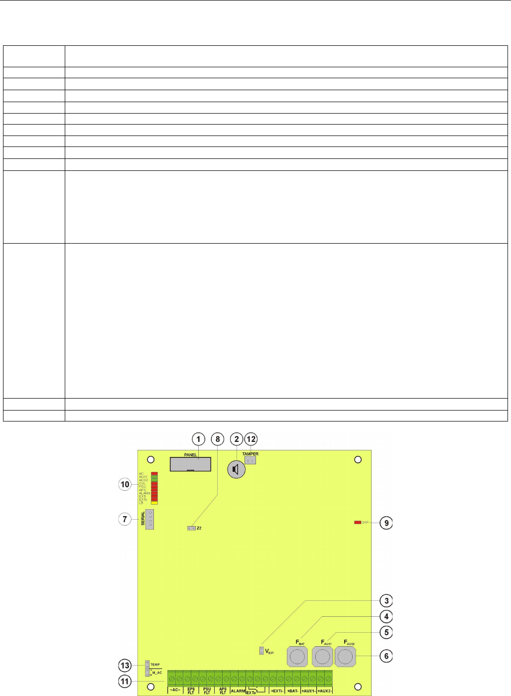
4.3. Description of components and power supply terminals.
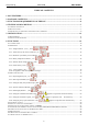
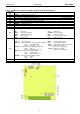
Table 1. Components of the Power supply PCB (Printed Circuit Board) (Fig. 2).
Component
No.
Description
[1] PANEL – optical indication connector
[2]
BUZZER – acoustic indication
(see section 6.3.4)
[3]
V
EXT
jumper
– polarization of the EXTi circuit
(see section 6.5)
[4]
F
BAT
– fuse in the battery circuit,
F6,3A / 250V
[5]
F
AUX1
– fuse in the AUX1 output circuit,
F5A / 250V
[6]
F
AUX2
– fuse in the AUX2 output circuit,
F5A / 250V
[7] SERIAL – communication port
[8]
Z2 jumper - temporary lock of the battery test
(see section 7.5)
[9]
OVP – overvoltage protection optical indication
(see section 6.8)
[10]
LEDs – optical indication:
AC – AC power
AUX1 – AUX1 output voltage
AUX2 – AUX2 output voltage
OVL – PSU overload
APS – battery failure
PSU – PSU failure
ALARM – collective failure
EXTi – EXTi input status
EXTo – EXTo relay output status
LB – battery charging
[11]
Terminals:
~AC~ – AC power input
EPS FLT – technical output of AC power failure indication
open = AC power failure
closed = AC power - O.K.
PSU FLT – technical output of PSU failure indication
open = failure
closed = PSU operation - O.K.
APS FLT – technical output of battery failure
open = battery failure
closed = battery status - O.K.
ALARM – technical output of collective failure
open = failure
closed = O.K.
EXTo – controlled relay output
EXTi – input of collective failure
+BAT- – terminals for connecting the battery
+AUX1- – AUX1 power output
(+AUX1= +U, -AUX=GND)
+AUX2- – AUX2 power output
(+AUX2= +U, -AUX=GND)
[12]
TAMPER – antisabotage protection microswitch connector
(see section 6.6)
[13] Connector– for connecting the EMC filter
Fig. 2. The view of the PSU’s PCB.