
Operating instructions


www.pulsar.pl EN54-3A28 RED POWER
36
9. Technical parameters.
Electrical parameters (Table 12).
Mechanical parameters (Table 13).
Safety of use (Table 14).
Recommended types and sections of installation cables (Table 15)
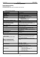
Table 12. Electrical parameters.
Functional class PN-EN 12101-10:2007 A
Mains supply 230V AC (-15%/+10%)
Current consumption 0,56A @230V AC
Power frequency 50Hz
PSU’s power 83W
Efficiency 84%
Output voltage at
20 ºC
22,0V÷ 27,6V DC – buffer operation
20,0V÷ 27,6V DC – battery-assisted operation
Output current Continuous operation
Output current Imax a=1,5A
Instantaneous operation
Output current Imax b=3A
Maximal resistance of the battery circuit 300mΩ
Ripple voltage 90mV p-p max.
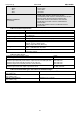
Current consumption by the PSU
during battery-assisted operation
I = 78mA
Caution ! If the power supply is connected with the
communication interface or fuse module, additional current
consumption should be considered.
Battery charging current 1,5A
Coefficient of temperature compensation of the
battery voltage
-40mV/ ºC (-5 ºC ÷ 40 ºC)
Low battery voltage indication Ubat < 23V, during battery mode
Overvoltage protection OVP
U>30,5V, disconnection of the output voltage ( AUX+
disconnection), automatic return
Short-circuit protection SCP
F5A – current limit, F
AUX
melting fuse (failure requires fuse
replacement)
Overload protection OLP Hardware - Software
Battery circuit protection SCP and reverse
polarity connection
F6,3A- current limit, F
BAT
melting fuse (failure requires fuse
replacement)
Deep discharge battery protection UVP U<20V (± 2%) – disconnection (+BAT) of the batteries,
TAMPER output indicating enclosure opening Microswitch TAMPER
- type – electronic, max 50mA/30V DC, galvanic isolation
1500V
RMS
- delay time approximately 10s/1m/10m/30m (+/-5%) –
configured from the LED panel
Technical outputs:
- EPS FLT; indicating AC power failure
- APS FLT; indicating battery failure
- PSU FLT; indicating PSU failure
- ALARM; indicating collective failure
- type – electronic, max 50mA/30V DC, galvanic isolation
1500V
RMS
EXTi technical input
Voltage „ON” – 10÷30V DC
Voltage „OFF” – 0÷2V DC
Level of galvanic isolation 1500V
RMS
EXTo relay output 1A@ 30V DC /50V AC
Optical indication:
- LEDs on the PCB of the power supply unit,
- LED panel
• output current readings
• output voltage readings: AUX1, AUX2
• resistance of the battery circuit
• mains supply voltage
• failure codes and history
Acoustic indication:
- piezoelectric indicator ~75dB /0,3m, switched from the LED
panel