
Operating instructions


www.pulsar.pl EN54-3A28 RED POWER
32
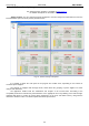
8. Remote monitoring (options: Wi-Fi, Ethernet, RS485, USB).
The PSU has been adjusted to operate in a system that requires a remote control of the parameters in a
monitoring centre. Transmitting data concerning PSU status is possible due to an additional, external
communication module responsible for communication in Wi-Fi, Ethernet or RS485 standard. The USB –TTL
interface enables the connection between the PSU and the computer.
Different connection topologies, presented later in this chapter, are only a part of possible communication
schemes. More examples can be found in the manuals dedicated to individual interfaces.
When installing optional features in the power supply unit, power supply current consumption, used
for the calculation of standby time, should be taken into account (see section 7.8.).
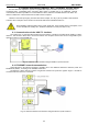
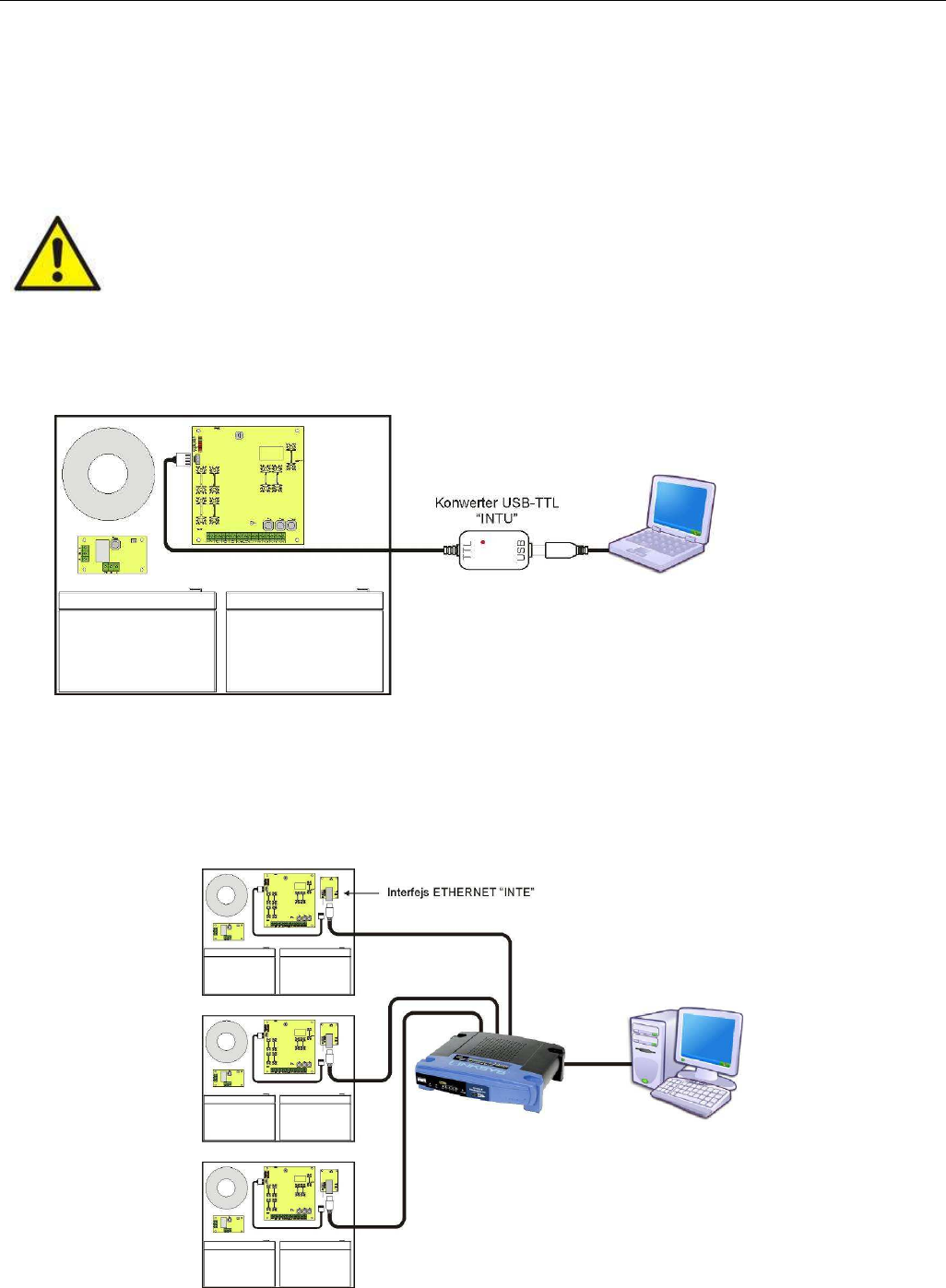
8.1. Communication via the USB-TTL interface.
The easiest way of communication between the PSU and the computer is provided by the USB-TTL "INTU”
interface. This interface allows direct connection between the computer and the PSU and is recognizable by the
operating system as a virtual COM port.
Fig. 15. USB-TTL communication using the USB-TTL „INTU” interface
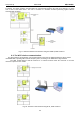
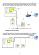
8.2. ETHERNET network communication.
Communication in the Ethernet network is possible due to the additional interfaces: Ethernet „INTE” and
RS485-ETH „INTRE”, according to the IEEE802.3 standard.
The Ethernet „INTE” interface features full galvanic isolation and protection against surges. It should be
mounted inside the enclosure of the PSU.
Fig. 16. Ethernet network communication using the Ethernet „INTE” interface.