
Operating instructions
www.pulsar.pl EN54-3A28 RED POWER
26
6.4. Technical outputs.
The PSU is equipped with galvanically isolated indication outputs changing status after a specified event:
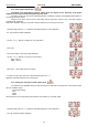
• EPS FLT – output indicating AC power loss.
The output indicates 230V AC power loss. Under normal status – with the 230V AC supply on, the output is
closed. In case of power failure, the PSU will switch the output into the open position after a time lag determined in
the „EPS” configuration menu (see section 6.3.3, Table 10).
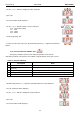
• APS FLT – output indicating battery failure.
The output indicates a failure in the battery circuit. Under normal status (during correct operation) the
output is closed. In case of failure, the PSU will switch the output into the open position. Failure can be triggered by
the following events:
- faulty batteries
- undercharged batteries
- disconnected batteries
- high resistance of the battery circuit
- battery voltage below 23V during battery-assisted operation
- battery fuse failure
- no continuity in the battery circuit
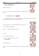
• PSU FLT – output indicating PSU failure.
The output indicates the PSU failure. Under normal status (during correct operation) the output is closed. In
case of PSU failure, it will switch into the open position. Failure can be triggered by the following events:
- U
AUX1, AUX2
output voltage below 26V
- U
AUX1, AUX2
output voltage over 29,2V
- battery charging circuit failure
- blown F
AUX1
or F
AUX2
fuse - exceeding the rated current of the PSU
- activation of overvoltage protection OVP
- mains supply voltage over 254V AC
- mains supply voltage below 195V AC
- too high ambient temperature of the batteries
- temperature sensor failure
- enclosure opening - TAMPER
- internal damage of the PSU
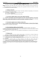
The technical outputs have been made with galvanic isolation between the PSU’s systems and the
attached devices.
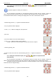
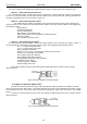
Fig. 10. Electrical diagram of technical outputs.
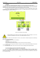
6.5. Input of collective failure: EXTi.
The EXT IN (external input) technical input indicating collective failure is intended for additional, external
devices that generate the failure signal. The voltage appearing at the EXT IN input will trigger PSU failure, storing
the information about the event in the internal memory and sending the signal about the failure to the ALARM
output.
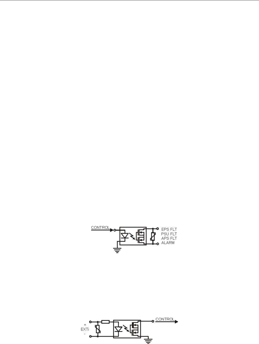
The EXT IN technical input has been made with galvanic isolation between the PSU’s systems and the
attached devices.
Fig. 11. Electrical diagram of the EXT IN input.