
Operating instructions


www.pulsar.pl EN54-3A28 RED POWER
2
TABLE OF CONTENTS
1. PSU FEATURES:...............................................................................................................................4
2. PACKAGE CONTENTS....................................................................................................................5
3. FUNCTIONAL REQUIREMENTS OF THE PSU...........................................................................6
4. TECHNICAL DESCRIPTION..........................................................................................................7
4.1.
G
ENERAL DESCRIPTION
.................................................................................................................................................7
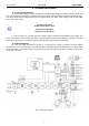
4.2.
B
LOCK DIAGRAM
..........................................................................................................................................................7
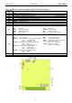
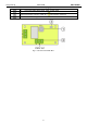
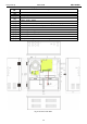
4.3.
D
ESCRIPTION OF COMPONENTS AND POWER SUPPLY TERMINALS
. ....................................................................................8
5. INSTALLATION..............................................................................................................................11
5.1.
R
EQUIREMENTS
. .........................................................................................................................................................11
5.2.
I
NSTALLATION PROCEDURE
. ........................................................................................................................................12
6. FUNCTIONS. ...................................................................................................................................13
6.1.
C
ONTROL
P
ANEL
. .......................................................................................................................................................13
6.2.
M
AIN MENU
................................................................................................................................................................14
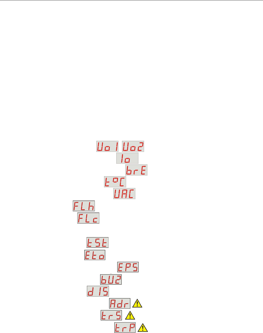
6.2.1. Voltage indicator „Uo1”, „Uo2” ...................................................................................15
6.2.2. Total current of the receivers indicator „Io” .......................................................................................15
6.2.3. Resistance of the battery circuit indicator „bre” ................................................................................15
6.2.4. Battery temperature indicator „t°C” ................................................................................................15
6.2.5. 230V AC mains voltage indicator „UAC” .........................................................................................15
6.2.6. Failure history “FLh” .......................................................................................................................15
6.2.7. Current failures „FLc” ....................................................................................................................16
6.2.8. List of failure codes and information messages.....................................................................................................17
6.3.
PSU
CONFIGURATION
..................................................................................................................................................19
6.3.1. Performing battery test „tSt” .............................................................................................................20
6.3.2. EXTo output ON/OFF„Eto” ...............................................................................................................21
6.3.3. Setting the delay time for EPS output „EPS” .......................................................................................21
6.3.4. Acoustic indication ON/OFF „bUZ" ...................................................................................................22
6.3.5. LED Display Dimmer „dIS" .............................................................................................................23
6.3.6. Setting the communication address Adr” applies to cooperation with PowerSecurity..................24
6.3.7. Setting the transmission speed „trS” applies to cooperation with PowerSecurity...................24
6.3.8. Setting the parity of the transmission “trP” applies to cooperation with PowerSecurity..............25
6.4.
T
ECHNICAL OUTPUTS
. .................................................................................................................................................26
6.5.
I
NPUT OF COLLECTIVE FAILURE
:
EXT
I
. ........................................................................................................................26
6.6.
I
NDICATION OF THE ENCLOSURE OPENING
-
TAMPER. .................................................................................................27
6.7.
I
NCREASING THE NUMBER OF OUTPUTS WITH OPTIONAL
EN54-LB4
OR
EN54-LB8
FUSE MODULES
................................28
6.8.
O
VERVOLTAGE PROTECTION OF THE
PSU
OUTPUT
OVP................................................................................................28
6.9.
PSU
OVERLOAD
..........................................................................................................................................................29
6.10.
I
NDICATION OF EXCEEDING
I
MAX A CURRENT
.............................................................................................................29
6.11.
S
HORT
-
CIRCUIT OF THE
PSU
OUTPUT
.........................................................................................................................29