
Operating instructions
www.pulsar.pl EN54-3A28 RED POWER
15
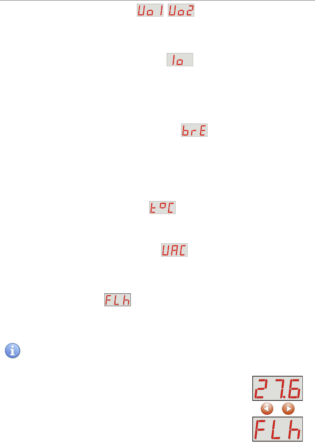
6.2.1. Voltage indicator „Uo1”, „Uo2”
Voltage indicator displays the measured output voltage at the AUX1 and AUX2 outputs. If the voltage drops
below 26V or exceeds 29.2V, the PSU will indicate a failure.
The resolution of voltage measurement is 0.1V and should be treated with caution. If a greater accuracy is
required, use a multimeter.
6.2.2. Total current of the receivers indicator „Io”
Total output current indicator displays the measured output current drawn from the AUX1 and AUX2
outputs. If the value of total current is exceeded, the power supply unit will indicate a failure.
Io = IAUX1 + IAUX2
The resolution of current measurement is 0.1A and should be treated with caution. If a greater accuracy is
required, use a multimeter.
6.2.3. Resistance of the battery circuit indicator „bre”
Resistance of the battery circuit indicator displays the measured resistance of the battery circuit of the
PSU. The resistance value is affected by:
- The quality of the batteries
- The quality of the battery cables and connections
- The quality of the FBAT fuse
If the resistance drops below 300 mΩ, the power supply unit will indicate a failure.
The measurement result is displayed with a resolution of 0.01 ohm.
6.2.4. Battery temperature indicator „t°C”
Battery voltage indicator displays the measured temperature of the batteries. The temperature is used by
the automatic control system for compensation of the battery charging voltage.
The measurement result is displayed with a resolution of 1°C.
6.2.5. 230V AC mains voltage indicator „UAC”
230V AC mains voltage indicator displays the measured mains voltage at the 230V AC mains terminals. If
the voltage drops below 195V AC or exceeds 254V AC, the power supply unit will indicate a failure.
The resolution of current measurement is 1V and should be treated with caution. If a greater accuracy is required,
use a multimeter.
6.2.6. Failure history “FLh”
.
The PSU remembers 30 last failures in non-volatile memory, which can be reviewed later.
In order to review the failures, use the "<" or ">" button to set the FLh parameter and confirm by pressing "OK".
The display will show the number of failure in the memory and its code. Pressing the "OK" button again will display
next failure in the memory.
The memory of the new power supply remembers the events that are the result of the efficiency tests
carried out at the production stage.
- press „<” or „>” button to set the „FLh” parameter on the display