
Operating instructions
www.pulsar.pl EN54-3A28 RED POWER
13
6. Functions.
6.1. Control Panel.
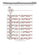
The PSU features a panel with buttons and LED display, enabling reading of all the available electrical
parameters. The panel buttons are used to select and confirm the parameters, which should be displayed.
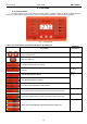
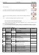
Fig. 7. Control panel.
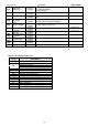
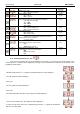
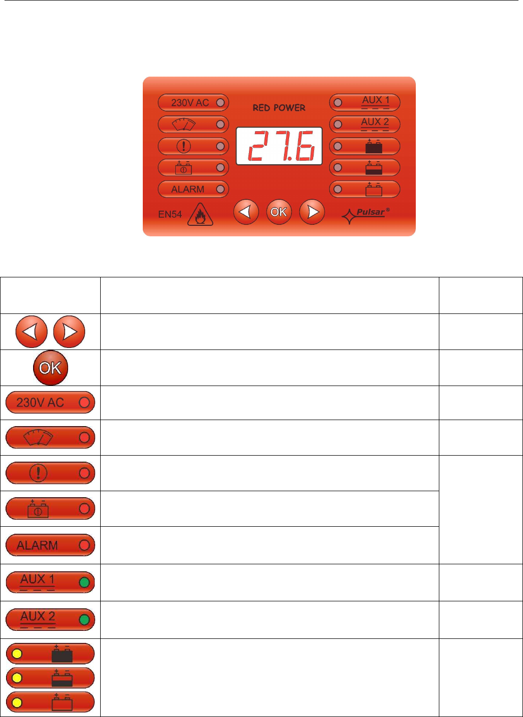
Table 6. The description of the buttons and LEDs of the LED panel.
Description
Additional
information
- moves the pointer on the screen
- next screen selection
- selection approval
- red LED indicating 230V AC voltage
- red LED indicating exceeding the Imax a current or power supply
overload
section
6.9, 6.10
- red LED indicating PSU failure
- red LED indicating battery failure
- red LED ALARM indicating collective failure
section
6.2.3
- green LED AUX1 indicating power at the AUX 1 output of the PSU
- green LED AUX2 indicating power at the AUX 2 output of the PSU
- three yellow LEDs indicating approximate battery charge level