
Operating instructions
www.pulsar.pl EN54-3A28 RED POWER
11
5. Installation.
5.1. Requirements.
The PSU is to be mounted by a qualified installer, holding relevant permits and licenses (applicable and
required for a given country) for 230V/AC in and low-voltage installations.
As the power supply is designed for a continuous operation and is not equipped with a power-
switch, therefore, an appropriate overload protection in the power supply circuit should be provided. Moreover, the
user should be informed how to disconnect the power supply unit from the mains supply (usually by assigning an
appropriate fuse in the fuse box). The electrical system shall be made in accordance with applicable standards
and regulations. The power supply should operate in a vertical position in order to provide free and
convectional air flow through ventilating holes of the casing.
As the PSU performs a periodic battery test, measuring the resistance of connections, special attention
should be paid to the proper connection of the cables to the batteries. Installation cables should be firmly
connected to the battery side terminals and to the power supply connector.
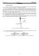
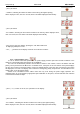
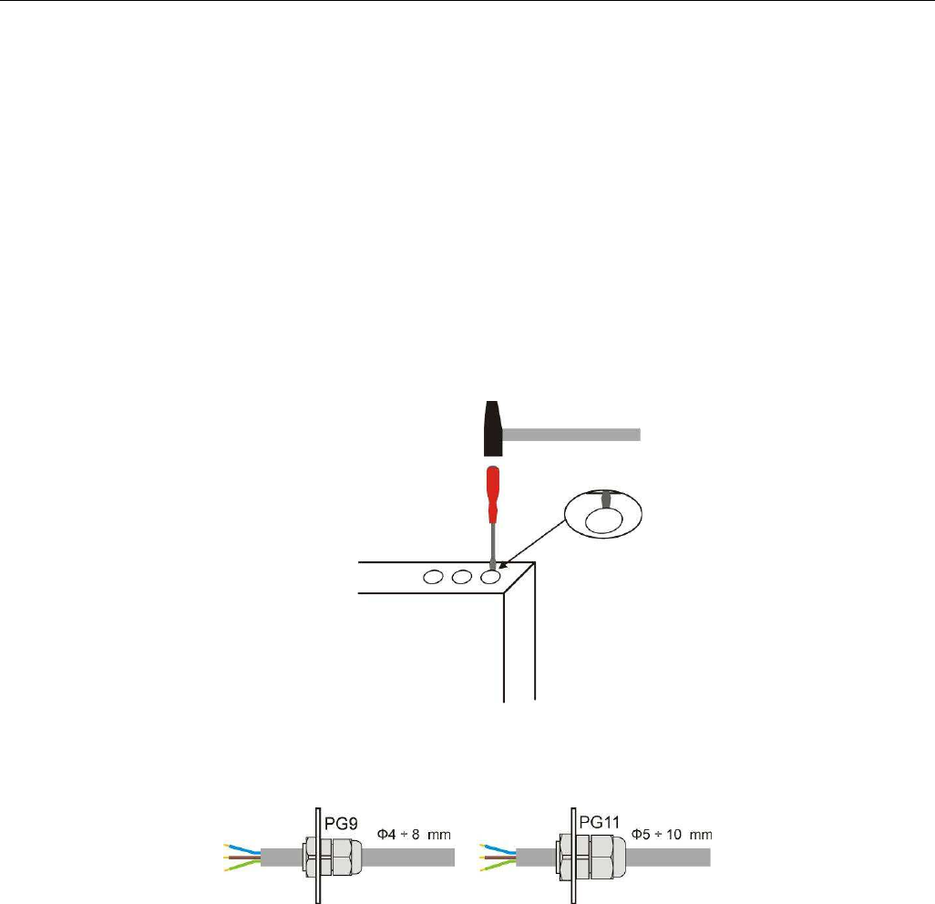
The side walls of the housing include the embossings, which should be used to carry out installation
cables. Use a blunt instrument to make an opening for cable gland from the outside of the housing. Then, carefully
mount the cable gland, protecting the PSU from water penetration, in the opening.
Fig. 5. The method of forming an opening for cable gland.
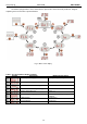
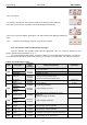
The PSU is fitted with PG9 and PG11 cable glands. Gland size should be chosen depending on the cross-
section of the cable. Single cable gland can be used for only one wire.
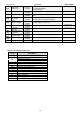
Fig. 6. Recommended types and sections of installation cables PG9 and PG11 for cable glands.