
Data Sheet
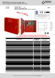

Pulsar
®
EN54/LED series power supply unit
Power supply for fire alarm systems 27,6 V DC
Tel. +48-14-610-19-40, fax: +48-14- 610-19-50, www.pulsar.pl, e-mail:sales@pulsar.pl
W
H
D
Functional class EN 12101-10:2007
A
Mains supply
~230 V
Current consumption
0,56 A
Power frequency
50 Hz
PSU’s power
83 W
Efficiency
84%
Output voltage at 20 ºC
22,0 V÷ 27,6 V DC – buffer operation
20,0 V÷ 27,6 V DC – battery-assisted operation
Output current Continuous operation: Imax a=2 A
Instantaneous operation: Imax b=3 A
Maximal resistance of the battery circuit
300m Ohm
Ripple voltage
90mV p-p max.
Current consumption by the PSU
during battery-assisted operation
I = 78mA
Caution ! If the power supply is connected with the communication interface or
fuse module, additional current consumption should be considered.
Battery charging current
1 A
Coefficient of temperature compensation of the
battery voltage
-40mV/ ºC (-5 ºC ÷ 40 ºC)
Low battery voltage indication
Ubat < 23 V, during battery mode
Overvoltage protection OVP
U>30,5 V, disconnection of the output voltage ( AUX+ disconnection),
automatic return
Short-circuit protection SCP
F5 A – current limit, F
AUX
melting fuse (failure requires fuse replacement)
Overload protection OLP
Hardware - Software
Battery circuit protection SCP and reverse
polarity connection
F6,3 A- current limit, F
BAT
melting fuse (failure requires fuse replacement)
Deep discharge battery protection UVP
U<20 V (± 2%) – disconnection (+BAT) of the batteries,
TAMPER output indicating enclosure opening
Microswitch TAMPER
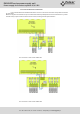
Technical outputs:
- EPS FLT; indicating AC power failure
- APS FLT; indicating battery failure
- PSU FLT; indicating PSU failure
- ALARM; indicating collective failure
- type – electronic, max 50mA/30 V DC, galvanic isolation 1500 V
RMS
- delay time approximately 10s/1m/10m/30m (+/-5%) – configured from the LED
panel
- type – electronic, max 50mA/30V DC, galvanic isolation 1500 V
RMS
- type – relay: 1 A@ 30 V DC/50 V AC
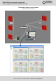
CAUTION! In Fig.2 the set of contacts shows a potential-free status of the
relay, which corresponds to power supply failure.
EXTi technical input
Voltage „ON” – 10÷30 V DC
Voltage „OFF” – 0÷2 V DC
Level of galvanic isolation 1500 V
RMS
EXTo relay output
1 A@ 30 V DC /50 V AC
Optical indication:
- LEDs on the PCB of the power supply unit,
- LED panel
· output current readings
· output voltage readings: AUX1, AUX2
· resistance of the battery circuit
· mains supply voltage
· failure codes and history
Acoustic indication:
- piezoelectric indicator ~75 dB /0,3 m
Fuses:
- F
MAINS
- F
BAT
- F
AUX1
- F
AUX2
T 3,15 A / 250 V
F 6,3 A / 250 V
F 5 A / 250 V
F 5 A / 250 V
Additional equipment
(not included)
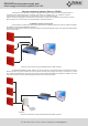
- RS485 „INTR” interface; RS485 communication
- Ethernet „INTE” interface; Ethernet communication
- RS485-Ethernet “INTRE” interface; RS485-Ethernet communication
Operating conditions
2nd environmental class ( EN12101-10:2007), -5
o
C÷75
o
C
Enclosure
Steel plate DC01 1,2mm, color: RAL 3001 (red)
Enclosure dimensions
W=420 H=420 D+D
1
=102 + 8 [+/- 2mm]
W
1
=425 H
1
=425 [+/- 2mm]
Net/gross weight
8,3/ 9,4 kg
Fitting battery
2x17 Ah/12 V (SLA) max.
400 x 180 x 95mm (WxHxD) max
Closing
Key lock
Certificates, declarations, warranty
Certificate of constancy of performance CNBOP-PIB,
Certificate of approval CNBOP-PIB,
CE, RoHS, 5 years from the production date
Notes
The enclosure does not adjoin the mounting surface so that cables can be led.
Convection cooling.