
Operating instructions

6
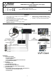
3. Indication of the device operation.
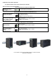
3.1 Optical indication of the switch operation (see Table 8).
Table 8. Indication of the switch operation
OPTICAL INDICATION OF THE SWITCH's POWER SUPPLY
GREEN LED LIGHT (Power)
Indication of the switch's
power supply
OFF – no power supply of the switch
ON – power supply on, normal operation
OPTICAL INDICATION OF THE SWITCH's POWER SUPPLY (1÷4)
DIODA LED ZIELONA (PoE)
Indication of the PoE power
supply at the RJ45 ports
OFF- no power supply at the RJ45 port (the device is not connected or not compliant with
the IEEE802.3af standard)
ON – supply at the RJ45 port
Blinking – short-circuit or output overload
YELLOW LED LIGHT (LINK)
The connection status of LAN
devices, 10MB/s or 100Mb/s
and data transmission
OFF- no connection
ON - the device is connected; 10Mb/s or 100Mb/s
Blinking – data transmission
OPTICAL INDICATION AT THE UPLINK PORT
GREEN LED LIGHT
OFF- no connection
ON – the device is connected; 10Mb/s or 100Mb/s
YELLOW LED LIGHT (LINK)
The connection status of
LAN devices, 10MB/s or
100Mb/s
and data transmission
OFF- no data transmission
ON - the device is connected: 10Mb/s or 100Mb/s
Blinking – data transmission
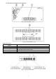
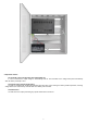
The example of mounting the DSB54 switch on a DIN rail (TH35)
(DIN rail not included)