
Operating instructions

3
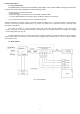
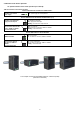
1.3 Description of components and connectors.
Fig. 2. The view switch'a - front.
Fig. 2b. The view switch'a - rear.
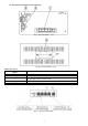
Table 1. (See Fig. 2)
Component No.
(Fig. 2)
Description
[1]
Switch PoE
[2]
buffer switched mode power supply
[3]
Power supply connector of the PSU – L, N
PE protective connector (electric shock)
[4]
BAT +, BAT - battery output
[5]
Holder for DIN rail (80x50)
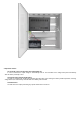
Fig. 3. The view of the switch.