
Data Sheet


Suggested Application
V-V+Bat-Bat+
Load
A : 12V
B : 24V
Battery
++
--
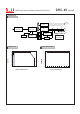
1.Backup connection for AC interruption
(1) Please refer to Fig1.1 for suggested connection.
The power supply charges the battery and provides energy to the load at the same time when AC mains is OK.
The battery starts to supply power to the load when AC mains fails.
Fig 1.1 Suggested system connection
Pin6(Pin8) Short with output -V
External voltage and R
(The max. Sink is 30mA and 50V)
R
V
AC OK (Battery low)
Fig 2.2 Internal circuit of AC OK (Battery Low), via TTL open collector
40W Single Output with Battery Charger (UPS Function)
DRC-40 series
File Name:DRC-40-SPEC 2014-10-22
2.Alarm signal for AC OK and battery low
(1) Alarm signal is sent out through " AC OK " & " Battery Low " pins.(TTL open collector output is provided for standard model, and relay contact output is provided as
optional model.)
(2) An external voltage source is required for this function. The maximum applied voltage is 50V and the maximum sink current is 30mA. Please refer to Fig 2.2.
(3) Table2.1 explains the alarm function built in the power supply
Function
Output of alarm
Low (0.3V max. at 30mA)
Low (0.3V max. at 30mA)
High or open (External applied voltage 50V max.)
High or open (External applied voltage 50V max.)
Description
The signal is "Low" when the power supply turns ON.
The signal is "Low" when the voltage of battery is under A:11V, B:22V.
The signal is "High" when the voltage of battery is above A:11V, B:22V.
The signal turns to be "High" when the power supply turns OFF.
AC OK
Battery Low
Table 2.1 Explanation of alarm signal
DC OK
+V ADJ
+